
Antenna structure and wireless communication device having said antenna structure

An antenna structure and antenna technology, applied in the direction of the connection of the antenna grounding switch structure, the antenna grounding device, the antenna support/installation device, etc. The effect of broadband performance

Active Publication Date: 2021-11-23
MOBILE DRIVE NETHERLANDS BV
View PDF0 Cites 0 Cited by
  • Summary
  • Abstract
  • Description
  • Claims
  • Application Information

AI Technical Summary

Problems solved by technology

When designing the antenna for each specific frequency band, the frequency offset due to the very small size of the millimeter-wave antenna and poor processing will affect the performance of the antenna

Method used


Image

  • Antenna structure and wireless communication device having said antenna structure
  • Antenna structure and wireless communication device having said antenna structure
  • Antenna structure and wireless communication device having said antenna structure

Examples


Embodiment Construction

[0041] The following will clearly and completely describe the technical solutions in the embodiments of the present invention with reference to the accompanying drawings in the embodiments of the present invention. Obviously, the described embodiments are only some, not all, embodiments of the present invention.

[0042] In order to make the object, technical solution and advantages of the present invention clearer, the antenna structure and the wireless communication device having the antenna structure in the present invention will be further described in detail and related explanations below in conjunction with the accompanying drawings and embodiments.

[0043] Some embodiments of the present invention will be described in detail below in conjunction with the accompanying drawings. In the case of no conflict, the following embodiments and features in the embodiments can be combined with each other.

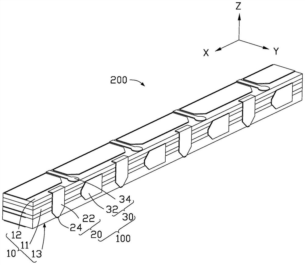
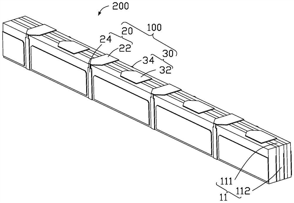
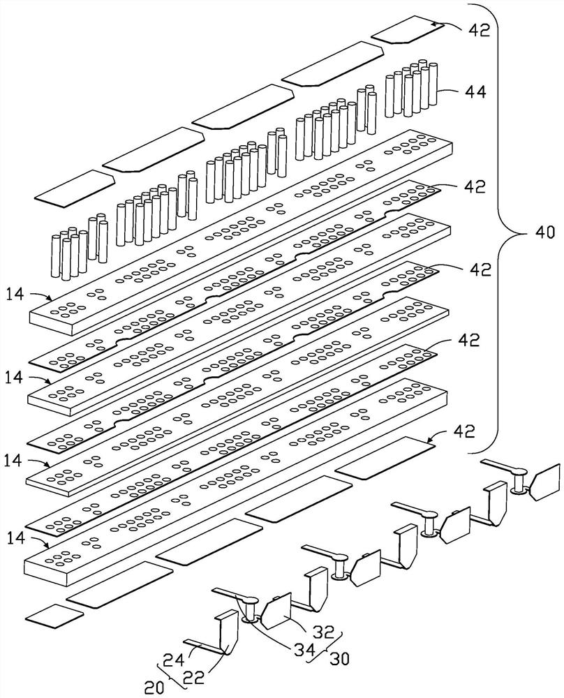
[0044] see figure 1 and figure 2 , a preferred embodiment of the presen...


PUM


Abstract

The present invention provides an antenna structure, which includes a plurality of first antenna units and a plurality of second antenna units arranged in a straight line, and one first antenna is arranged between every two adjacent second antenna units unit, each of the first antenna unit and each of the second antenna units is a single polarization direction, each of the first antenna units is a first polarization direction, and each of the second antenna units Both are the second polarization direction, and the first polarization direction and the second polarization direction are perpendicular to each other. The present invention also provides a wireless communication device with the antenna structure. In this way, ultra-wideband performance can be achieved, and interference caused by too short distances between adjacent antenna elements can be reduced.

Description

technical field [0001] The invention relates to an antenna structure and a wireless communication device with the antenna structure. Background technique [0002] At present, the communication frequency band of 5G millimeter wave covers 26.5GHz-40GHz, and the bandwidth of the frequency band is very wide. When designing the antenna for each specific frequency band, the frequency offset due to the very small size of the millimeter-wave antenna and poor processing will affect the performance of the antenna. In addition, due to the large radiation propagation loss of the millimeter-wave antenna, the antenna itself needs to increase its own gain through array combination as a compensation. How to arrange several antenna arrays in a limited space is a major problem in millimeter wave antenna design. Contents of the invention [0003] In view of the above, it is necessary to provide an antenna structure and a wireless communication device having the antenna structure. [0004]...

Claims


Application Information

Patent Timeline
Patent Type & Authority Patents(China)
IPC IPC(8): H01Q1/22H01Q1/38H01Q1/48H01Q1/50H01Q1/52H01Q21/00H01Q21/08H01Q21/24
CPCH01Q1/38H01Q1/50H01Q21/0006H01Q21/08H01Q21/24H01Q1/523H01Q1/48H01Q1/22H01Q25/001H01Q1/2283H01Q1/243
Inventor 陈国丞常建伟林铮陈佳林可加陈云汉
Owner MOBILE DRIVE NETHERLANDS BV
Learn More