Method and device for determining cell relationship
A cell relationship, cell technology, applied in the field of communications
- Summary
- Abstract
- Description
- Claims
- Application Information
AI Technical Summary
Problems solved by technology
Method used
Image
Examples
Embodiment 1
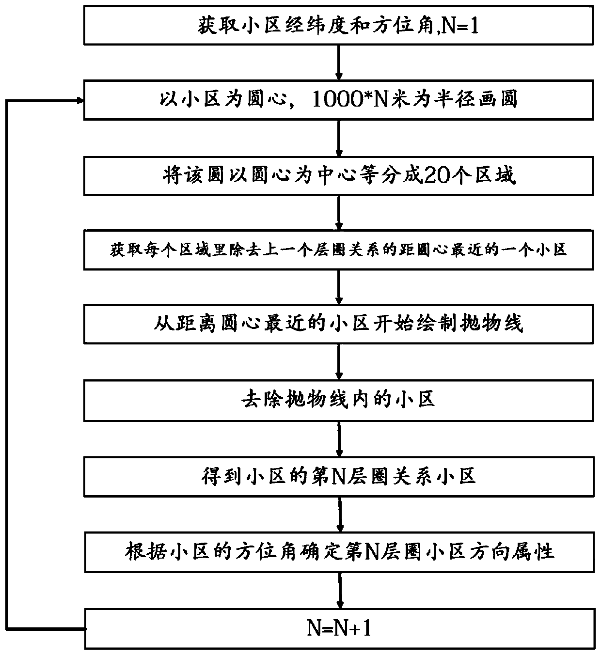
[0052] Embodiment 1: as Figure 1~5 As shown, the method for determining the cell relationship includes the following steps:
[0053](1) Obtain the latitude, longitude and azimuth of each cell;
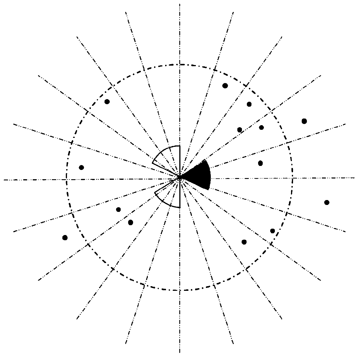
[0054] (2) Determining the scope of the layer circle: draw at least one circle with the planning community as the center of the circle, then set the radius of the first layer circle as M meters, and then expand a layer circle outwards, and the radius increases by M meters; (M is 2 times the average station Spacing, the general area can be set to M = 1000 meters), such as figure 2 shown
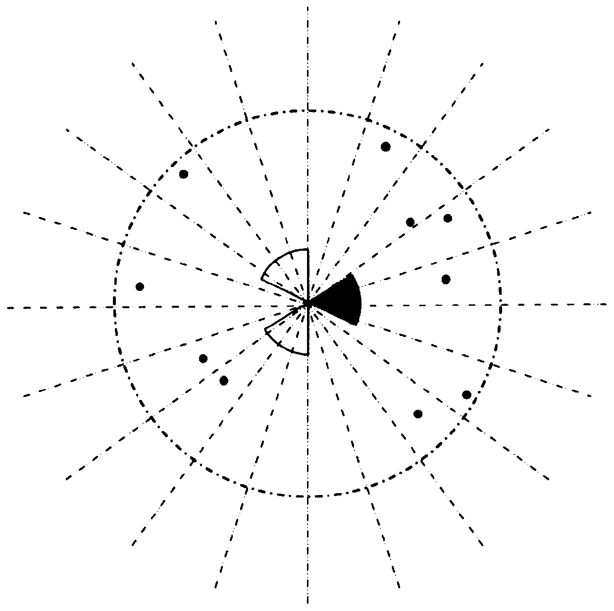
[0055] (3) Partitioning and drawing a parabola: take the planning area as the center of the circle, and take the north direction as the starting position, divide the circle drawn in step (2) into several fan-shaped areas, and then obtain the base station of each fan-shaped area closest to the center of the circle position, at this time, it is necessary to remove the previously selected base statio...
Embodiment 2
[0073] Embodiment 2: The device for determining the relationship between the cells includes an acquisition of latitude and longitude and azimuth unit 601, a calculation layer circle range and a partition unit 602, a drawing parabola unit 603, and a generation circle relationship unit 604, and the unit 601 for obtaining the latitude and longitude and azimuth angle The longitude, latitude and azimuth angle of the acquisition cell for the acquisition cell; the calculation layer circle range and partition unit 602 is used to calculate the layer circle;
[0074] The drawing parabola unit 603 is used to draw a parabola for the base station cells within the circle range, and exclude the base station cells within the parabola to avoid cell interference;
[0075] The generating layer circle relationship unit 604 is used to calculate the area attributes of the remaining cells after removing the base station cells that do not meet the requirements, and calculate the forward or backward ce...
Embodiment 3
[0076] Embodiment 3: In this embodiment, the method of Embodiment 1 and the device of Embodiment 2 are adopted, and a community in an area of a certain city is selected to illustrate the determination of the relationship between the communities; Figure 7 As shown in , take the cell pointed by the arrow as an example, and calculate the relationship between this cell and other surrounding cells;
[0077] (1) Obtain the latitude, longitude and azimuth of each cell from the engineering parameter table of the existing network;
[0078] (2) Draw a circle with the community as the center, calculate 3 layers of circles, and set the radius as 1000 meters, 2000 meters and 3000 meters respectively with the planned community as the center, such as Figure 8 shown;
[0079] (3) Partition and draw a parabola: take the planning area as the center and the north direction as the starting point, divide it into a fan-shaped area every 18°, and divide it into 20 fan-shaped areas in total, suc...
PUM
 Abstract
Description
Claims
Application Information
 - R&D
- Intellectual Property
- Life Sciences
- Materials
- Tech Scout
- Unparalleled Data Quality
- Higher Quality Content
- 60% Fewer Hallucinations
Browse by: Latest US Patents, China's latest patents, Technical Efficacy Thesaurus, Application Domain, Technology Topic, Popular Technical Reports.
© 2025 PatSnap. All rights reserved.Legal|Privacy policy|Modern Slavery Act Transparency Statement|Sitemap|About US| Contact US: help@patsnap.com


