Pipeline part flaring punch die and pipeline forming equipment

A flaring tube and mold technology, applied in forming tools, metal processing equipment, manufacturing tools, etc., can solve problems such as affecting the consistency of piping, positioning accuracy, post-process operations, product appearance defects and quality problems, and reducing production efficiency. , to reduce copper pipe cracking, solve insufficient weld penetration, and improve work efficiency.

Pending Publication Date: 2020-06-09
GREE ELECTRICAL APPLIANCE SHIJIAZHUANG +1
View PDF0 Cites 2 Cited by
  • Summary
  • Abstract
  • Description
  • Claims
  • Application Information

AI Technical Summary

Problems solved by technology

[0002] At present, the flared pipe parts produced by the flared mold in the pipeline workshop directly connect a large-angle transition part between the flared section and the unflared section, so that the matching copper pipe is prone to loosening or cracking under the action of external force. The pop-up phenomenon of copper pipes affects the consistency of piping, positioning accuracy and post-process operations. Such phenomena not only reduce production efficiency, but also easily cause appearance defects and quality problems of products

Method used


Image

  • Pipeline part flaring punch die and pipeline forming equipment
  • Pipeline part flaring punch die and pipeline forming equipment
  • Pipeline part flaring punch die and pipeline forming equipment

Examples


Embodiment Construction

[0031] In order to make the purpose, technical solutions and advantages of the embodiments of the present invention more clear, the technical solutions in the embodiments will be clearly and completely described below in conjunction with the drawings in the embodiments of the present invention. The following embodiments are used to illustrate the present invention , but not to limit the scope of the present invention.

[0032] In the description of the present invention, it should be noted that the orientation or positional relationship indicated by the terms "inner", "outer" and the like are based on the orientation or positional relationship shown in the drawings, and are only for the convenience of describing the present invention and simplifying the description. It is not intended to indicate or imply that the referred device or element must have a particular orientation, be constructed in a particular orientation, and operate in a particular orientation, and thus should no...


PUM


Abstract

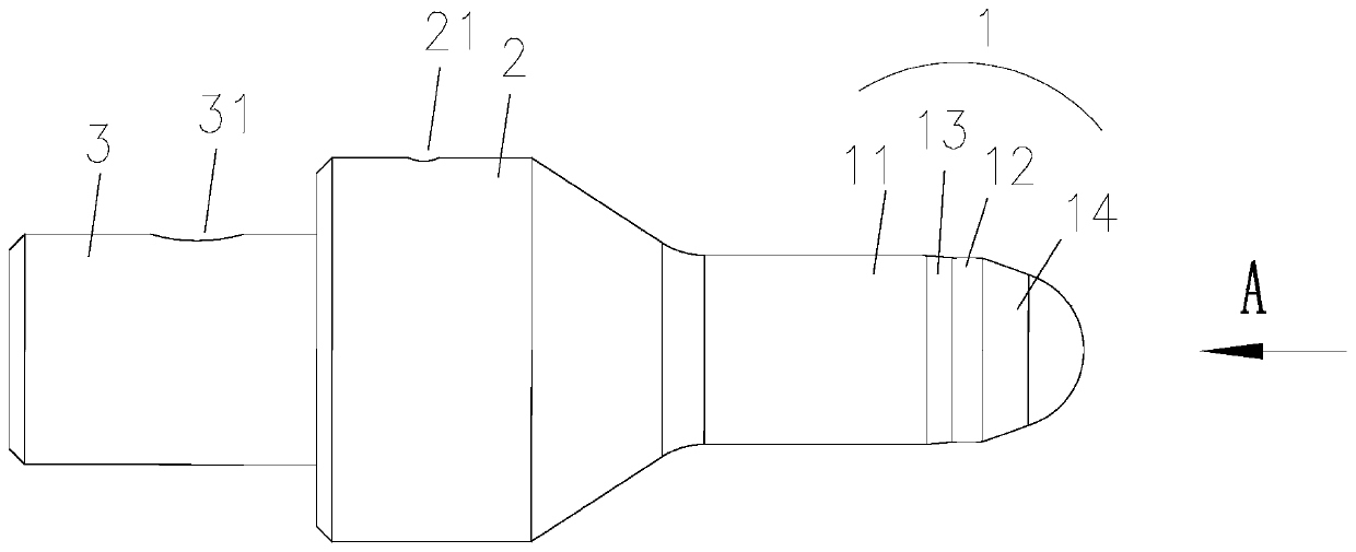
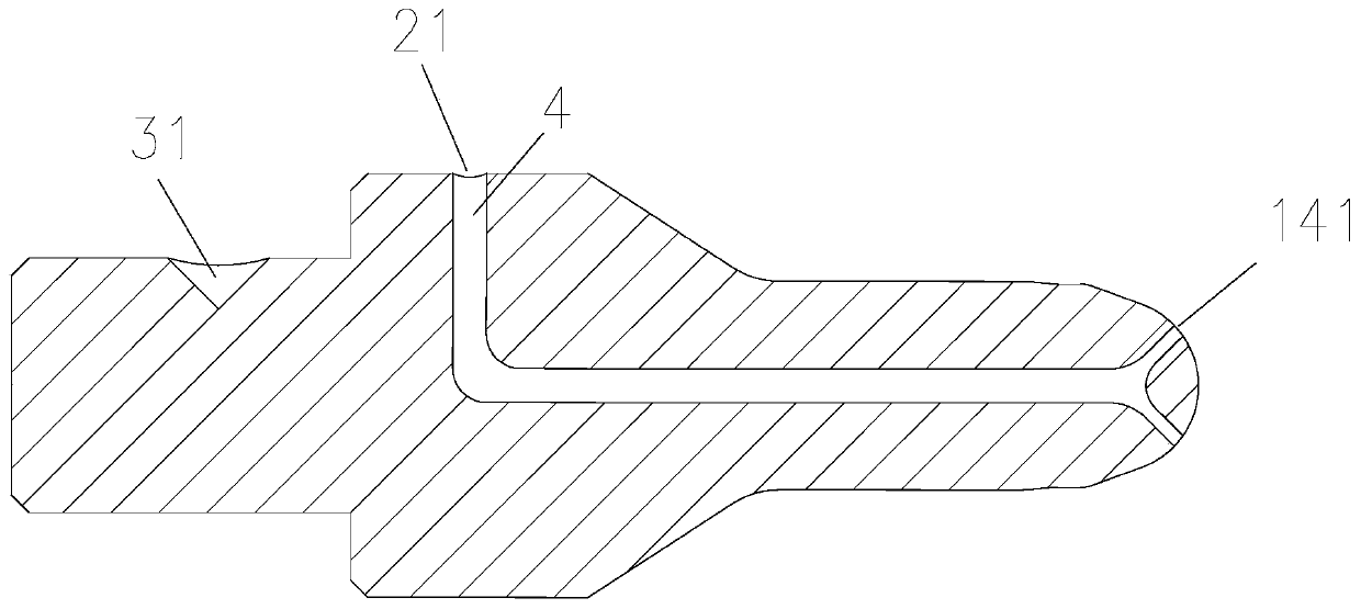
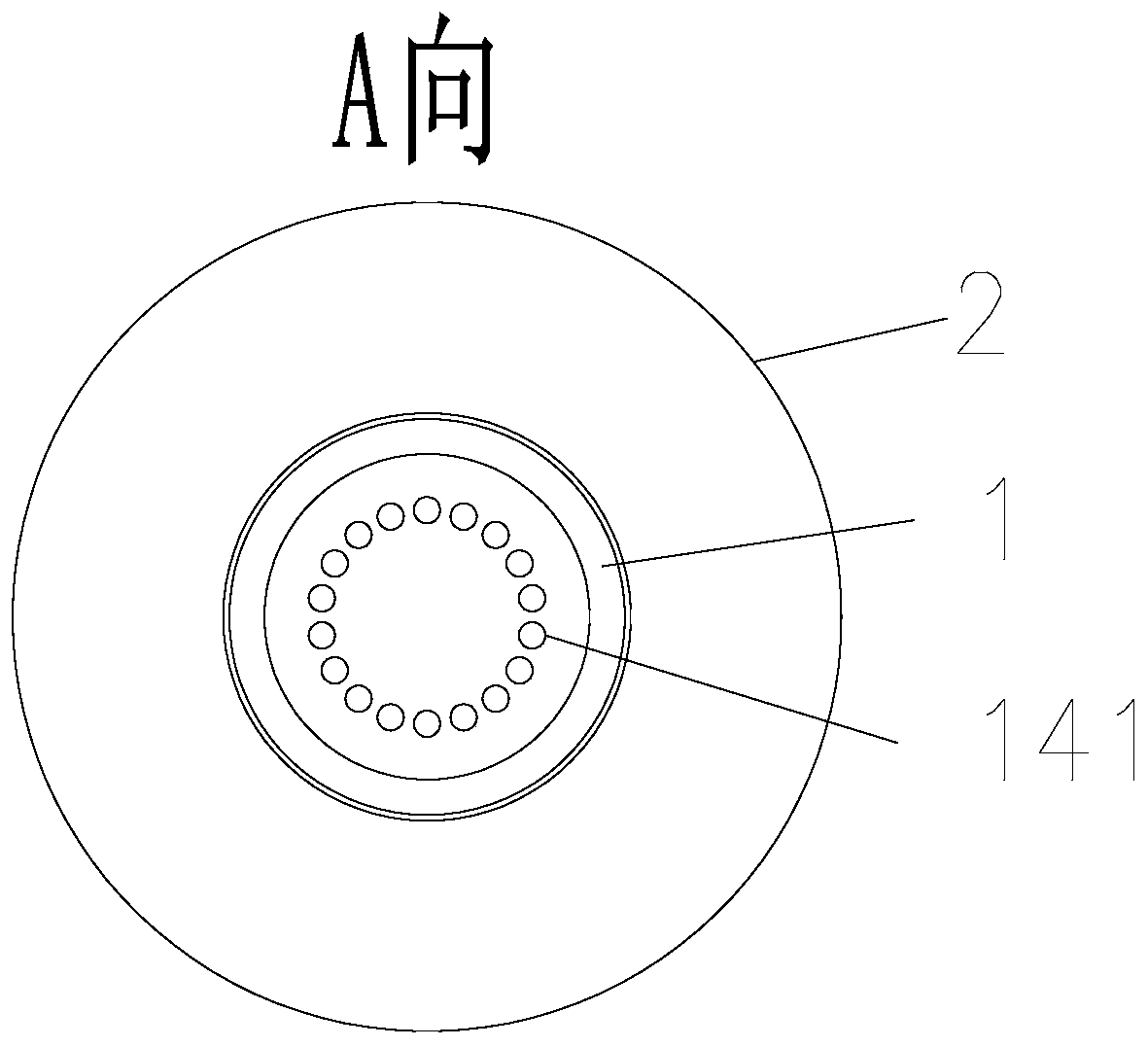
The invention belongs to the field of pipeline processing, and particularly relates to a pipeline part flaring punch die. The pipeline part flaring punch die comprises a die front section, wherein thedie front section is provided with a flaring part and an insertion part; a locking part is arranged between the flaring part and the insertion part; the size of the flaring part is larger than the internal size of a pipeline, and the size of the locking part is smaller than the internal size of the pipeline; and the pipeline sequentially passes through the insertion part, the locking part and theflaring part in the pipeline flaring process, and is subjected to flaring operation through the flaring part. The assembly consistency and positioning accuracy of assembly of the pipeline flared by the flaring die and a normal pipeline are effectively improved.

Description

technical field [0001] The invention belongs to the field of pipeline processing, and in particular relates to a pipeline piece flare punch die and pipeline forming equipment. Background technique [0002] At present, the flared pipe parts produced by the flared mold in the pipeline workshop directly connect a large-angle transition part between the flared section and the unflared section, so that the matching copper pipe is prone to loosening or cracking under the action of external force. The phenomenon of copper pipe ejection affects the consistency of piping, positioning accuracy and post-process operations. Such phenomena not only reduce production efficiency, but also easily cause appearance defects and quality problems of products. [0003] In view of this, the present invention is proposed. Contents of the invention [0004] The technical problem to be solved by the present invention is to provide a punch die for pipeline flare that has consistent piping and posit...

Claims


Application Information

Patent Timeline
Patent Type & Authority Applications(China)
IPC IPC(8): B21D41/02B21D37/10B21D37/01B21D37/18
CPCB21D37/01B21D37/10B21D37/18B21D41/02
Inventor 杨雷戎海梅孙刚尹亮亮张杰冯韶楠黄启苗立亚陈陶生刘永恩孙明举张阔张超敏于思贺冯晓堤王宁宁王培龙陈玉城李彭真
Owner GREE ELECTRICAL APPLIANCE SHIJIAZHUANG
Why Eureka
Try Eureka