Universal fixture for horizontal clamping of fuel injection pump body

A fuel injection pump and clamping technology, which is used in clamping, manufacturing tools, positioning devices, etc., can solve the problems of high manufacturing cost of positioning fixtures, irregular shapes, and jamming during clamping, so as to reduce manufacturing costs and be widely used. flexibility and applicability, and the effect of reducing the labor intensity of clamping

Active Publication Date: 2021-10-26
CHONGQING HONGJIANG MACHINERY
View PDF8 Cites 0 Cited by
  • Summary
  • Abstract
  • Description
  • Claims
  • Application Information

AI Technical Summary

Problems solved by technology

[0002] The fuel injection pump body of the medium-speed diesel engine has many varieties and specifications, the body is large, the parts are heavy, and the shape is a special-shaped casting blank surface. For the processing of the oil holes and space inclined holes around the fuel injection pump body, special fixtures are generally used to achieve horizontal clamping Processing, after the outer circle of the part positioning is matched with the positioning hole of the fixture, the screw and the pressure plate are used to press the part for processing; this kind of clamping method needs to lift the part by driving and then insert the outer circle of the part into the positioning hole to position the outer circle. The circle needs to pass through the positioning hole of the fixture. Since the fit clearance is generally 0.01-0.04mm, and because the parts are heavy and irregular in shape, it is easy to cause strain and scratches on the positioning outer circle, and it is easy to cause jamming during the clamping process. The heavier the part, the more prone to seizure
Parts of different specifications need to design and manufacture a set of special fixtures, and holes of the same part with different angles also need to redesign a set of special fixtures, so that a large number of special fixtures will be produced for series products, and the design and manufacture of positioning fixtures is very costly and efficient. Low

Method used


Image

  • Universal fixture for horizontal clamping of fuel injection pump body
  • Universal fixture for horizontal clamping of fuel injection pump body
  • Universal fixture for horizontal clamping of fuel injection pump body

Examples


Embodiment Construction

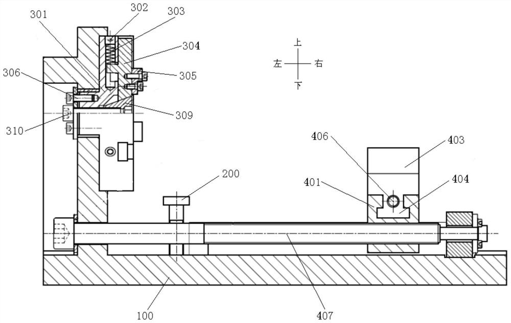
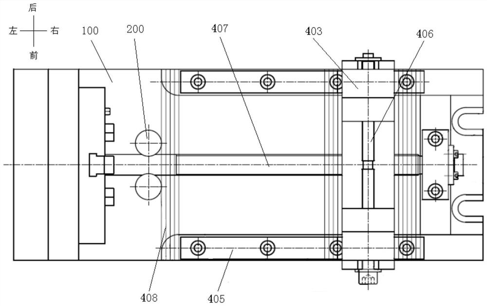
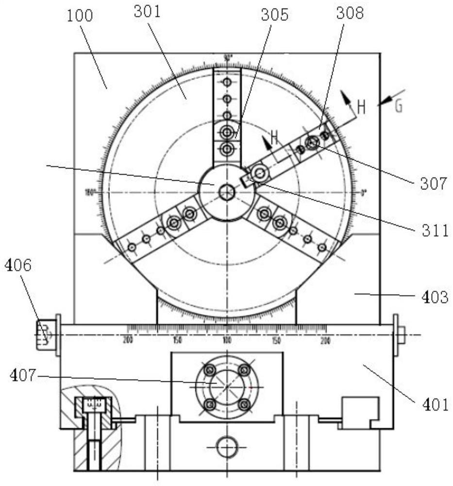
[0027] like Figure 1-Figure 10As shown, the universal fixture for horizontal clamping of the fuel injection pump body in this embodiment includes a base 100, and also includes a positioning mandrel device, an adjusting push rod 200 and a V-shaped frame fixed on the base 100 in sequence from left to right; The positioning mandrel device includes a centering chuck for positioning the center hole of the fuel injection pump body 500 and a positioning pin 307 for positioning the positioning hole of the fuel injection pump body 500, and the centering chuck includes a chuck The disc body 301, the claw drive mechanism and N movable claws, the claw drive mechanism is arranged on the chuck body 301, and the N movable claws are arranged on the chuck body 301 in a circumferential distribution , the jaw drive mechanism can drive N movable jaws to move synchronously in the radial direction; the chuck body 301 is arranged on the base 100, and the positioning pin 307 can adjust the installat...


PUM


Abstract

The invention discloses a universal fixture for horizontal clamping of a fuel injection pump body, which comprises a base, and also includes a positioning mandrel device, an adjusting push rod and a V-shaped frame fixed on the base in sequence from left to right; the positioning mandrel The device includes a centering chuck for positioning the middle hole of the fuel injection pump body and a positioning pin for positioning the positioning hole of the fuel injection pump body. The centering chuck includes a chuck body, a jaw driving mechanism and N movable jaws, the jaw driving mechanism is arranged on the chuck body, and the N movable jaws are arranged on the chuck body in a circumferential distribution, and the jaw driving mechanism can drive N The movable claws move synchronously in the radial direction; the chuck body is arranged on the base, and the positioning pin is arranged on the chuck body in a manner that the installation position can be adjusted in the radial direction; the V-shaped The frame includes a sliding block and two supporting blocks; the adjusting push rod and the V-shaped frame can provide support for the outer circle of the fuel injection pump body.

Description

technical field [0001] The invention relates to the technical field of mechanical manufacturing positioning fixtures, in particular to a universal fixture for horizontally clamping a fuel injection pump body. Background technique [0002] The fuel injection pump body of the medium-speed diesel engine has many varieties and specifications, the body is large, the parts are heavy, and the shape is a special-shaped casting blank surface. For the processing of the oil holes and space inclined holes around the fuel injection pump body, special fixtures are generally used to achieve horizontal clamping Processing, after the outer circle of the part positioning is matched with the positioning hole of the fixture, the screw and the pressure plate are used to press the part for processing; this kind of clamping method needs to lift the part by driving and then insert the outer circle of the part into the positioning hole to position the outer circle. The circle needs to pass through t...

Claims


Application Information

Patent Timeline
Patent Type & Authority Patents(China)
IPC IPC(8): B23Q3/06
CPCB23Q3/062
Inventor 骆云兵吴克兵
Owner CHONGQING HONGJIANG MACHINERY
Why Eureka
Try Eureka