
Balance weight tensioning device of belt conveyor

A technology of tensioning device and counterweight, which is applied in the direction of conveyors, transportation and packaging, etc., can solve the problems of endangering the safety of personnel and equipment, the total length of the belt, and belt slippage, and achieve stable operation protection and tensile elongation protection. Effect

Pending Publication Date: 2020-06-09
ZENITH STEEL GROUP CORP
View PDF0 Cites 0 Cited by
  • Summary
  • Abstract
  • Description
  • Claims
  • Application Information

AI Technical Summary

Problems solved by technology

[0003] The characteristic of the fixed manual tightening screw is that the tension force of the belt is relatively small. It is mainly used in workplaces where the total length of the belt is short or the space is small and the heavy hammer type automatic tensioner cannot be installed. Its advantages are space saving and low cost. , the disadvantage is that it will slip once it is overloaded or the belt is loose
[0004] The characteristic of the heavy hammer type automatic tensioning is to use the weight of the heavy hammer to adjust the tension force, which is mainly used in the workplace with long belt length and open space; its advantages: under normal circumstances, the tension force can be automatically adjusted to meet the normal operation , Disadvantages: When the heavy hammer is too heavy, it will affect the service life of the belt cementing head. When the heavy hammer is too light, the belt will slip and cannot meet the normal operation. Once the belt cementing head breaks accidentally, the heavy hammer will fall freely and endanger the safety of personnel and equipment itself.

Method used


Image

  • Balance weight tensioning device of belt conveyor
  • Balance weight tensioning device of belt conveyor

Examples


Embodiment Construction

[0015] The present invention is described in further detail now in conjunction with accompanying drawing. These drawings are all simplified schematic diagrams, which only illustrate the basic structure of the present invention in a schematic manner, so they only show the configurations related to the present invention.

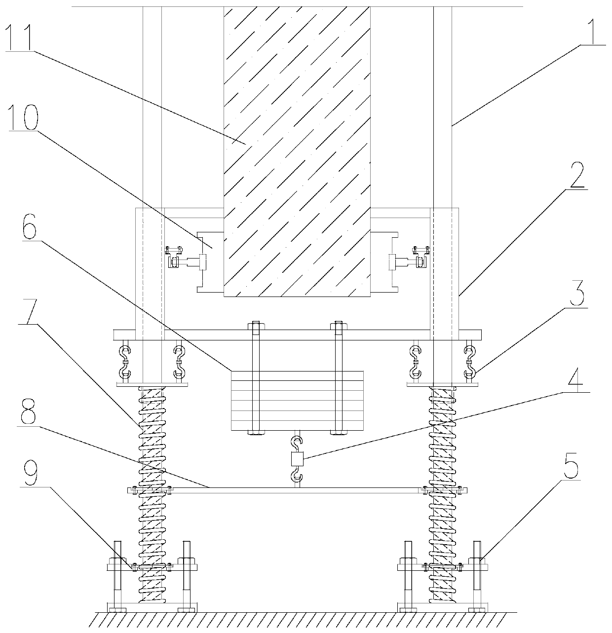
[0016] Such as figure 1 As shown, a belt conveyor counterweight tensioning device provided by the present invention includes a conveyor belt 11, the conveyor belt 11 is arranged on a reversing roller 10, and the reversing roller 10 is arranged on a frame 2, and the frame 2 is arranged on a left-right symmetrical On the column 1, the bottom end of the column 1 is installed on the ground through a fixed block, the bottom of the column 1 is covered with a spring 7, and the top of the spring 7 is connected to the frame 2 through the hook 3, and the hook 3 serves as a link between the spring 7 and the frame 2. function, it is convenient for the spring 7 to tighten...


PUM


Abstract

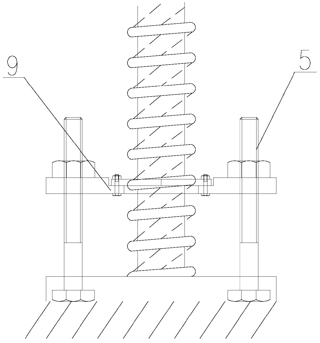
The invention relates to the technical field of metallurgical equipment, in particular to a balance weight tensioning device of a belt conveyor. The device comprises a conveyor belt. The conveyor beltis arranged on a redirection roller, the redirection roller is arranged on a frame, and the frame is arranged on columns which are symmetric in the left-right direction. The bottom ends of the columns are installed on the ground through fixing blocks, springs sleeve the bottoms of the columns, and the tops of the springs are connected with the frame through lifting hooks. The bottoms of the springs are provided with adjustment press plates, the two ends of each adjustment press plate are provided with adjustment screws for adjusting the tensioning degree of the springs, and a balance weight is hoisted on the bottom of the frame. According to the balance weight tensioning device, based on the length of the conveyor belt and the demand of the tensioning force, the tensioning pull force of the conveyor belt is adjusted and displayed. The balance weight tensioning device has an important protection effect on the service life of a cementation head of the conveyor belt, the stretching elongation ratio of the conveyor belt and the stable operation.

Description

technical field [0001] The invention relates to the technical field of metallurgical equipment, in particular to a belt conveyor counterweight tensioning device. Background technique [0002] In the steel industry, sintering is the first production process, and the conveyor belt conveyor is one of the many equipments. The stable operation of the conveyor belt conveyor is an important part of ensuring the entire production process. Currently, there are two types of tensioning structures for belt conveyors: fixed manual tensioning screw tensioning and heavy hammer automatic tensioning. [0003] The characteristic of the fixed manual tightening screw is that the tension force of the belt is relatively small. It is mainly used in workplaces where the total length of the belt is short or the space is small and the heavy hammer type automatic tensioner cannot be installed. Its advantages are space saving and low cost. , the disadvantage is that it will slip once it is overloaded ...

Claims


Application Information

Patent Timeline
IPC IPC(8): B65G23/44B65G15/62
CPCB65G15/62B65G23/44
Inventor 孟凡挺周孝平
Owner ZENITH STEEL GROUP CORP
Learn More