Sintering flue gas heating denitration system and sintering flue gas heating denitration method

A sintering flue gas and denitrification technology, which is applied in chemical instruments and methods, separation methods, gas treatment, etc., can solve the problems that affect the long-term stable operation of the system, low temperature of sintering flue gas, high humidity, etc. Low emission and reduced heat transfer effect

Inactive Publication Date: 2020-06-30
JIANGSU KEHANG ENVIRONMENT ENG TECH
View PDF0 Cites 0 Cited by
  • Summary
  • Abstract
  • Description
  • Claims
  • Application Information

AI Technical Summary

Problems solved by technology

The sintering flue gas after desulfurization has low temperature and high humidity, and needs to be heated to reach the temperature required for denitrification. If it directly enters the GGH heat exchanger, it may foul and affect the long-term stable operation of the system.

Method used


Image

  • Sintering flue gas heating denitration system and sintering flue gas heating denitration method

Examples


Embodiment Construction

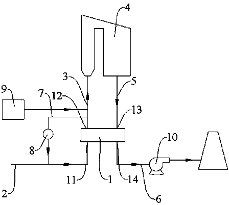
[0024] The present invention will be further described below in conjunction with the accompanying drawings and specific embodiments, so that those skilled in the art can better understand the present invention and implement it, but the examples given are not intended to limit the present invention.

[0025] Such as figure 1 As shown, a sintering flue gas heating and denitrification system includes a GGH heat exchanger 1. The GGH heat exchanger 1 has a cold air chamber and a hot air chamber for mutual heat exchange. Both ends of the cold air chamber have cold smoke inlets 11 and cold air The smoke outlet 12, the hot gas chamber has a hot smoke inlet 13 and a hot smoke outlet 14, the cold smoke inlet pipe 2 is connected to the cold smoke inlet 11, and the cold smoke outlet 12 passes through the cold smoke outlet pipe 3 Connect the smoke inlet of the SCR reactor 4, the smoke outlet of the SCR reactor 4 is connected to the hot smoke inlet 13 through the hot smoke inlet pipe 5, the...


PUM


Abstract

The invention discloses a sintering flue gas heating denitration system and a sintering flue gas heating denitration method. The system comprises a GGH heat exchanger, an SCR reactor, a circulating fan and a heating furnace, wherein a cold air chamber and a hot air chamber which exchange heat with each other are arranged in the GGH heat exchanger, and heat exchange is conducted on flue gas entering the SCR reactor and flue gas exhausted by the SCR reactor. The method comprises the following steps that S1, original sintering flue gas enters the cold air chamber of the GGH heat exchanger and then is exhausted, and temperature rising is conducted; S2, the heated flue gas is subjected to denitration and dust removal through alkali liquor spraying; S3, the flue gas subjected to denitration anddust removal enters the hot air chamber of the GGH heat exchanger, is cooled after exchanging heat with the flue gas in the cold air chamber, and the cooled flue gas is discharged; and S4, the flue gas in the cold air chamber and the flue gas in the hot air chamber are heated after heat exchange, and part of the heated flue gas and the original sintering flue gas are mixed and then circulated backto the cold air chamber. According to the invention, the denitration temperature is controlled by adjusting the circulation proportion, so that the denitration effect is guaranteed, and ultra-low emission is achieved.

Description

technical field [0001] The invention relates to the technical field of metallurgy and environmental protection, in particular to a system and method for raising the temperature of sintering flue gas and denitration. Background technique [0002] Sintering flue gas is a complex gas containing multiple pollutants, which needs to be dedusted, desulfurized, and denitrified. The sintering flue gas after desulfurization has low temperature and high humidity, and needs to be heated to reach the temperature required for denitrification. If it directly enters the GGH heat exchanger, scaling may occur, which will affect the long-term stable operation of the system. Contents of the invention [0003] The present invention aims to solve the above technical problems to a certain extent. [0004] In view of this, the present invention provides a sintering flue gas heating denitrification system and method, which adjusts the circulation ratio, controls the denitrification temperature, e...

Claims


Application Information

Patent Timeline
Patent Type & Authority Applications(China)
IPC IPC(8): B01D53/86B01D53/56
CPCB01D53/005B01D53/8631B01D53/8696B01D2258/0283
Inventor 刘怀平洪国军吴小兵贾福强崔士龙
Owner JIANGSU KEHANG ENVIRONMENT ENG TECH
Why Eureka
Try Eureka