A combined pre-embedded hook and its construction method
A construction method and combined technology, applied in the direction of load hanging components, buildings, building structures, etc., can solve the problems of inaccurate burying position, hanging hooks, etc., and achieve beautiful quality, accurate installation position and simple operation. Effect
- Summary
- Abstract
- Description
- Claims
- Application Information
AI Technical Summary
Problems solved by technology
Method used
Image
Examples
Embodiment 1
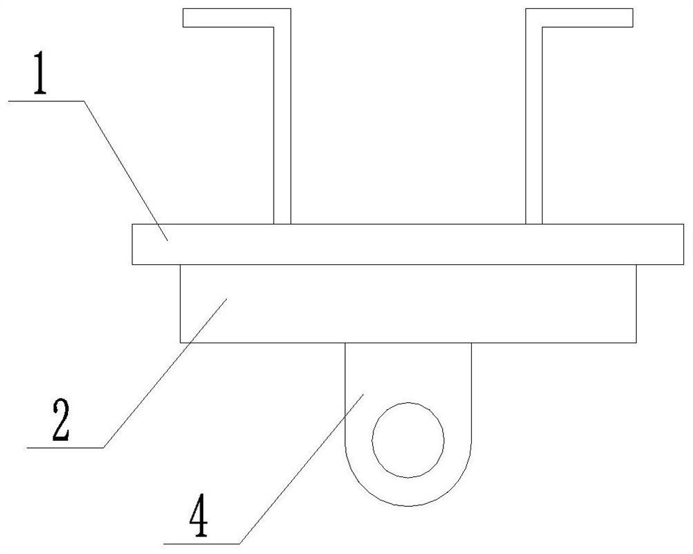
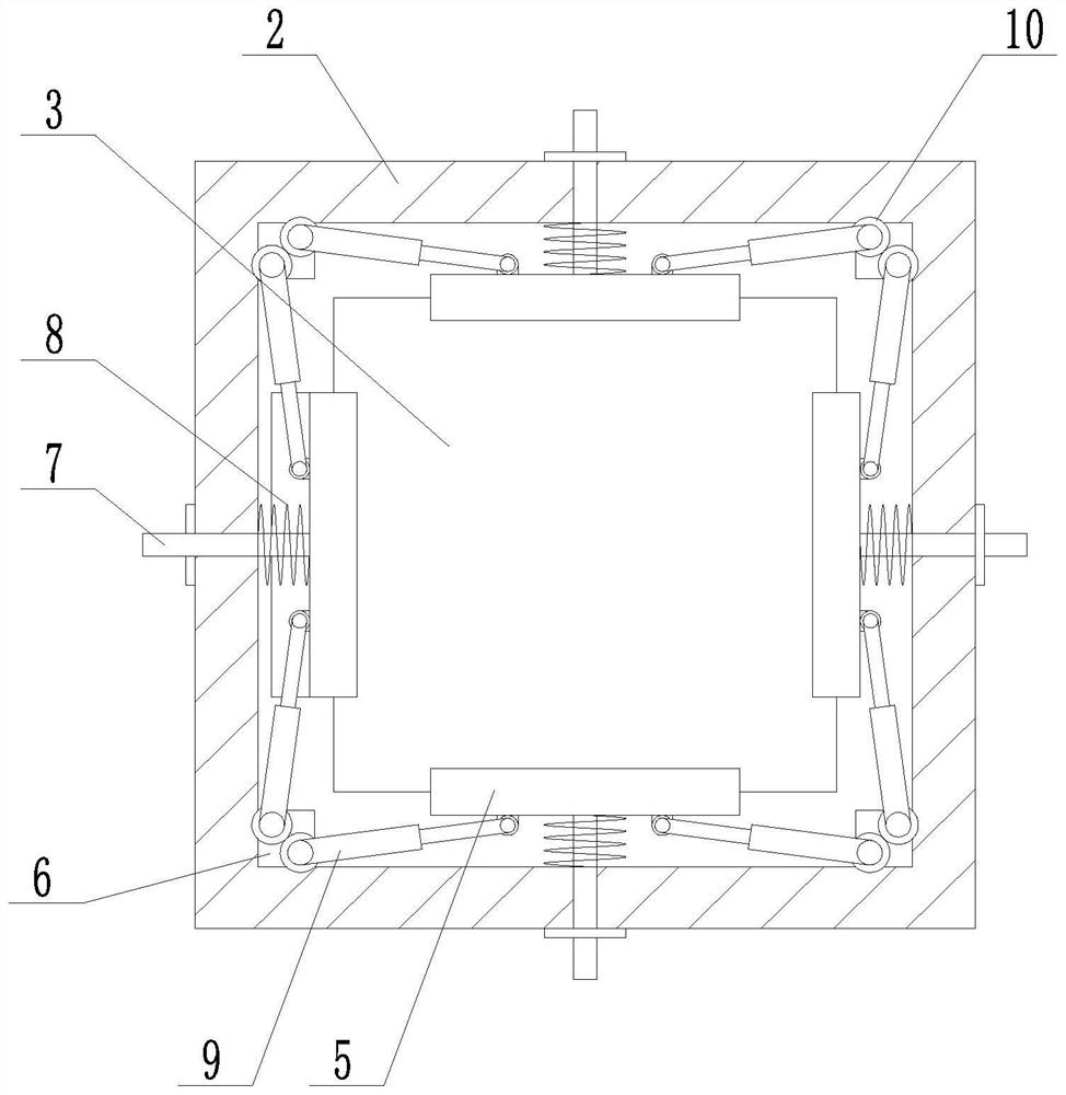
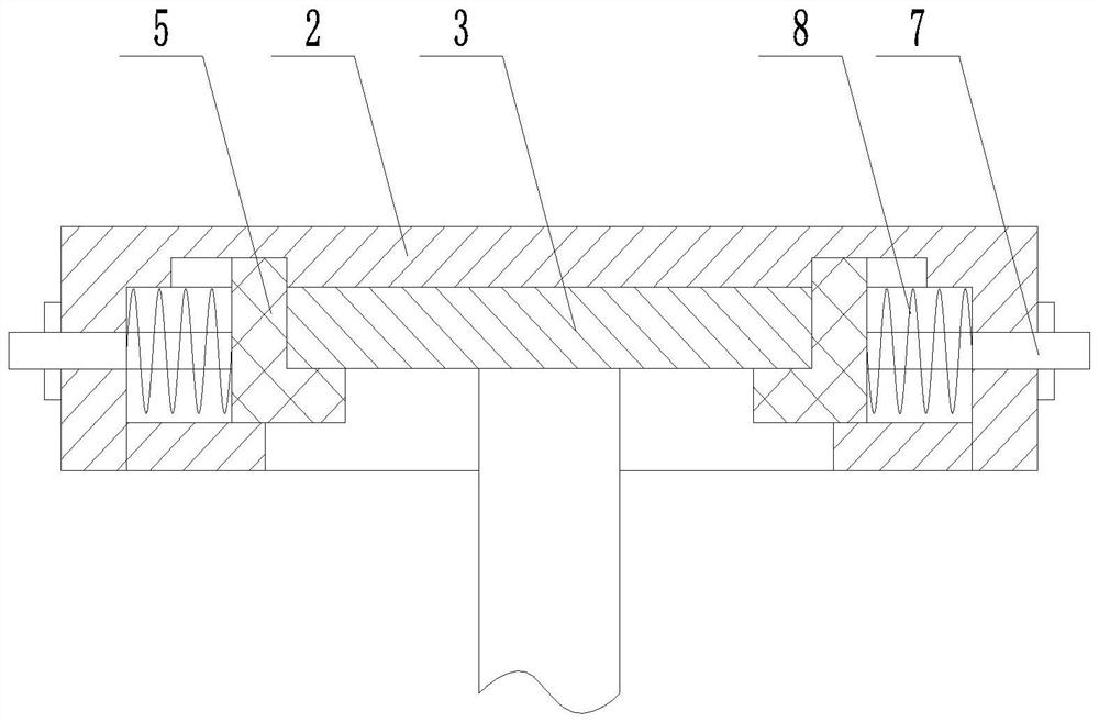
[0029] Such as Figure 1 to Figure 3 As shown, a combined pre-embedded hook includes an embedded steel plate 1 pre-embedded in the interior of the concrete through an anchor. The lower surface of the embedded steel plate 1 is fixedly connected with a groove box 2, and the bottom of the groove box 2 is open Setting, the slot box 2 is provided with a positioning unit, the inside of the slot box 2 is provided with a hanging plate 3, the hanging plate 3 is integrally connected with a web 4, and the bottom of the web 4 is provided with a hanging hole, and the slot box 2 is connected with the hanging plate through the positioning unit. Plate 3 realizes the fixed connection.
[0030] In a further preferred solution in this embodiment, the positioning unit includes a positioning plate 5 and a fixing seat 6, and multiple sets of the positioning plate 5 (inverted L-shaped structure) and the fixing seat 6 are arranged, and the positioning plate 5 and the fixing seat 6 are arranged crossw...
Embodiment 2
[0031] Embodiment 2: A construction method of a combined pre-embedded hook, comprising the following steps:
[0032] S1. First, weld the pre-embedded steel plate 1 and the tank box 2 as a whole, and the pre-embedded steel plate 1 is reserved in the concrete;
[0033] S2. After the concrete reaches a certain strength, after removing the formwork, adjust any fixed rod 7 to pull outward, the positioning plate 5 moves outward with the fixed rod 7 to drive the rotating rod to rotate, and a rotating rod located on the same fixed seat 6 passes through The gear 10 meshes to drive another rotating rod to rotate, and at the same time drives the adjacent positioning plates 5 to move outward, so that all the positioning plates 5 move to the side close to the inner wall of the tank box 2;
[0034] S3, the hanging board 3 is inserted into the tank box 2 from the side of the opening of the tank box 2, and then all the positioning claws of its fixing rod 7 are released to move to the hanging ...
Embodiment 3
[0036] Such as figure 1 , Figure 4 to Figure 6 As shown, the difference from Embodiment 1 is that the positioning unit includes a limit frame 11, a locking member 12 and a connecting hole 13, the limit frame 11 is integrally connected to the inner bottom end of the tank box 2, and the inner opening of the limit frame 11 The size is compatible with the hanging plate 3. The locking member 12 is connected to the limit frame 11 by threads. The locking member 12 can be adjusted vertically. The connecting holes 13 are provided at the four corners of the hanging plate 3. After the plate 3 is rotated by 45°, the locking member 12 matches the connecting hole 13 to fix the hanging plate 3 .
[0037] In a further preferred solution in this embodiment, an arc-shaped track 14 is provided on the inner top surface of the tank box 2, and two symmetrical positioning pins 16 are slidably connected in the arc-shaped track 14, and a positioning pin 16 is provided on the hanging plate 3. Holes ...
PUM
 Abstract
Description
Claims
Application Information
 - R&D
- Intellectual Property
- Life Sciences
- Materials
- Tech Scout
- Unparalleled Data Quality
- Higher Quality Content
- 60% Fewer Hallucinations
Browse by: Latest US Patents, China's latest patents, Technical Efficacy Thesaurus, Application Domain, Technology Topic, Popular Technical Reports.
© 2025 PatSnap. All rights reserved.Legal|Privacy policy|Modern Slavery Act Transparency Statement|Sitemap|About US| Contact US: help@patsnap.com


