Direct-connection drill rod for limiting conditions

A technology for extreme working conditions and drill pipes, which is applied in the field of direct-connected drill pipe joints, and can solve problems such as thread cross-threading, joint box buckle expansion, root fracture, etc.

Pending Publication Date: 2020-06-12
EXPLORATION TECH RES INST OF CHINESE ACADEMY OF GEOLOGICAL SCI
View PDF0 Cites 1 Cited by
  • Summary
  • Abstract
  • Description
  • Claims
  • Application Information

AI Technical Summary

Problems solved by technology

In recent years, with the rise of ultra-deep scientific drilling and deep-sea scientific drilling, extreme working conditions such as high temperature, high pressure, high stress, and no riser have put forward higher requirements on the performance of drill pipes. Conventional drill pipes can no longer meet the severe working conditions. Due to

Method used


Image

  • Direct-connection drill rod for limiting conditions
  • Direct-connection drill rod for limiting conditions
  • Direct-connection drill rod for limiting conditions

Examples


Embodiment Construction

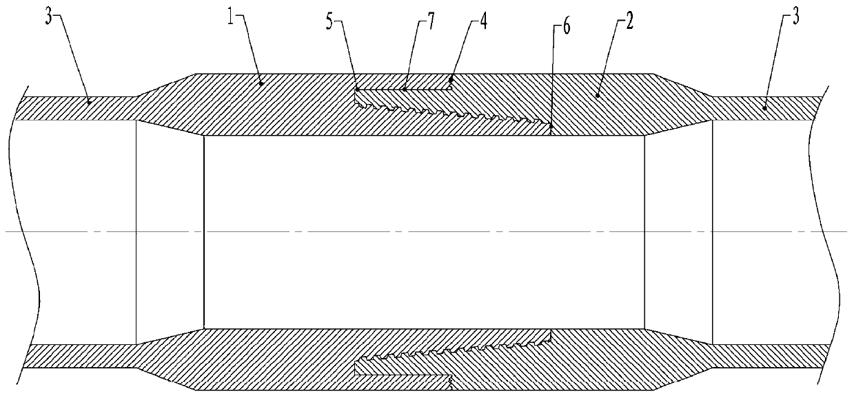
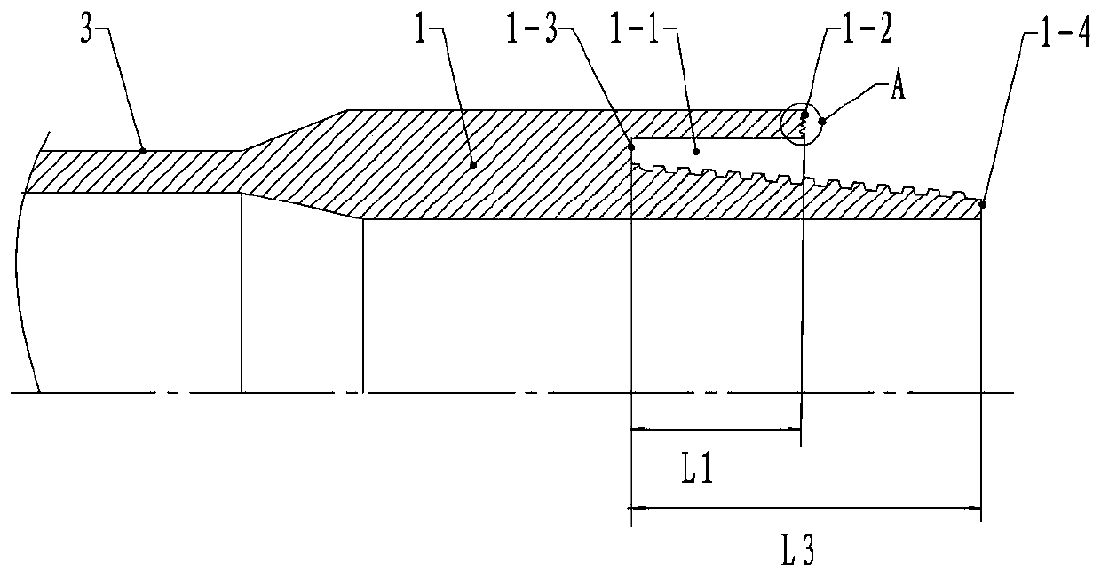
[0022] see figure 1 , figure 2 with Figure 4 , the present invention comprises a drill pipe body 3 and a male joint 1 and a female joint 2 connected by taper pipe threads, the male joint and the drill pipe body 3 connected thereto are of an integral structure, and the female joint and the drill pipe body 3 connected thereto are of an integral structure, so that The weak points of the drill string are reduced, improving the overall safety of the drill string. An outer pipe section is arranged on the outside of the tapered pipe thread section of the male joint, and an annular groove 1-1 is formed between the outer pipe section and the tapered pipe thread section of the public joint. The annular groove is from the middle part of the tapered pipe thread section of the male joint to the bottom of the tapered pipe thread section of the public joint. The female joint is provided with an insertion section 2-1, the insertion section is from the large end of the tapered pipe thread...


PUM


Abstract

The invention relates to a direct-connection drill rod for limiting conditions. The direct-connection drill rod comprises a male connector and a female connector, wherein an outer pipe section is arranged on the outer sides of threads of the male connector; an annular groove is formed between the outer pipe section and a threaded section of the male connector; the female connector is provided withan inserting section; the inserting section is inserted into the annular groove of the male connector in a matched manner; a male connector main shoulder is arranged at a tip of the outer pipe section; a male connector main auxiliary shoulder is arranged on the bottom surface of the annular groove; a male connector auxiliary shoulder is arranged at the small end of the male connector; a female connector main shoulder is arranged on the bottom surface of the inserting section of the female connector; a female connector main auxiliary shoulder is arranged at the large end of the female connector; a female connector auxiliary shoulder is arranged on the bottom surface of the threaded small end of the female connector; the male connector main shoulder and the female connector main shoulder form a main sealing surface; the male connector main auxiliary shoulder and the female connector main auxiliary shoulder form a main auxiliary sealing surface; and the male connector auxiliary shoulderand the female connector auxiliary shoulder form an auxiliary sealing surface. According to the direct-connection drill rod, the sealing performance of the connectors can be obviously improved, and the problem of thread stress concentration of a conventional structure is relieved; and thread stress is relatively uniformly distributed, and capability of resisting large bending deformation and torsional deformation of the drill rod is improved.

Description

technical field [0001] The invention relates to a drilling device, in particular to a direct-connected drill pipe joint used in extreme working conditions. Background technique [0002] The drill pipe is used as the link connecting the surface to the bottom of the well during the drilling process, and plays the role of mud transportation, torque transmission and sealing gasket. The stress state of the drill pipe is complex, and the failure of the drill pipe has become one of the main downhole accidents, especially the drill pipe joint, which is the main component of the drill pipe failure. In recent years, with the rise of ultra-deep scientific drilling and deep-sea scientific drilling, extreme working conditions such as high temperature, high pressure, high stress, and no riser have put forward higher requirements on the performance of drill pipes. Conventional drill pipes can no longer meet the severe working conditions. Due to the requirements of the conditions, accident...

Claims


Application Information

Patent Timeline
IPC IPC(8): E21B17/042
CPCE21B17/042E21B17/0423F16L15/004E21B17/046F16L15/001F16L15/04
Inventor 尹浩梁健李鑫淼孙建华李宽刘秀美
Owner EXPLORATION TECH RES INST OF CHINESE ACADEMY OF GEOLOGICAL SCI
Why Eureka
Try Eureka