Positioning reference signal configuration method, network equipment and terminal

A technology of positioning reference signal and configuration method, applied in the field of positioning reference signal configuration method, network equipment and terminal

Active Publication Date: 2020-06-12
VIVO MOBILE COMM CO LTD
View PDF7 Cites 14 Cited by
  • Summary
  • Abstract
  • Description
  • Claims
  • Application Information

AI Technical Summary

Problems solved by technology

[0021] The embodiment of the present invention provides a positioning reference signal configuration method, network equipment and terminal to solve the configuration problem of the PRS resource pattern in the NR system

Method used


Image

  • Positioning reference signal configuration method, network equipment and terminal
  • Positioning reference signal configuration method, network equipment and terminal
  • Positioning reference signal configuration method, network equipment and terminal

Examples


example 1

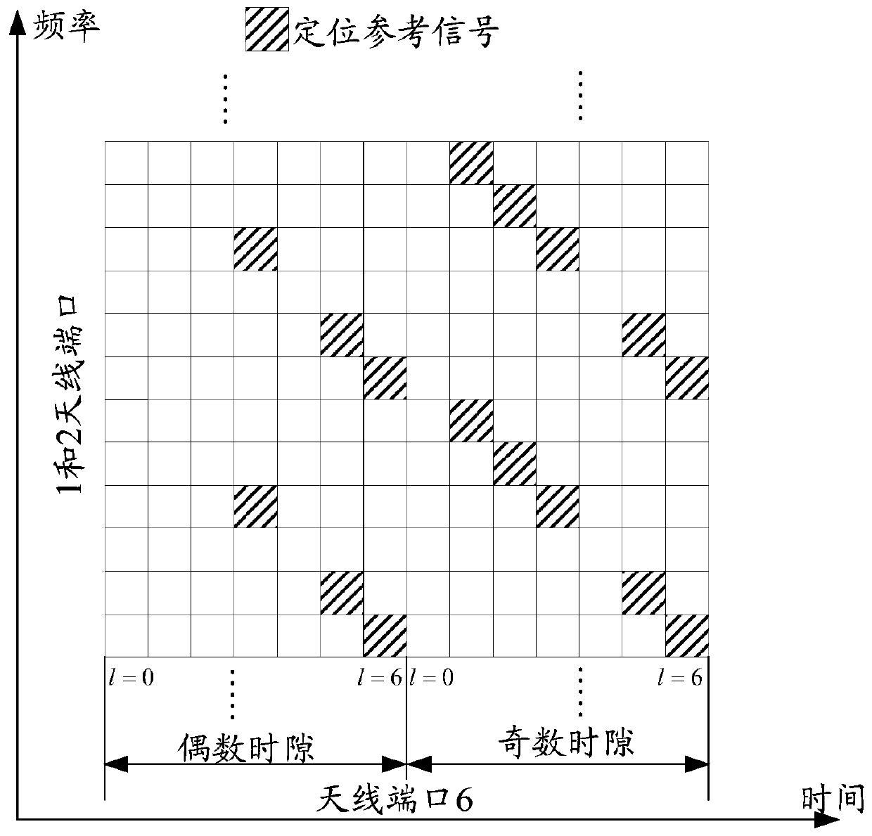
[0085] Example 1: Frequency domain density indicator comb-12, taking normal CP as an example

[0086] Such as Figure 5a As shown, the frequency domain density indicator comb-12 in the resource configuration information configured by the network configuration, the frequency domain offset is 1, the number of symbols included is 12, the first symbol position is 2, and the lowest frequency domain position in the first symbol is 0.

[0087] Such as Figure 5b As shown, the frequency domain density indicator comb-12 in the resource configuration information configured by the network configuration, the frequency domain offset is 2, the number of symbols included is 6, the first symbol position is 2, and the lowest frequency domain position in the first symbol is 0.

example 2

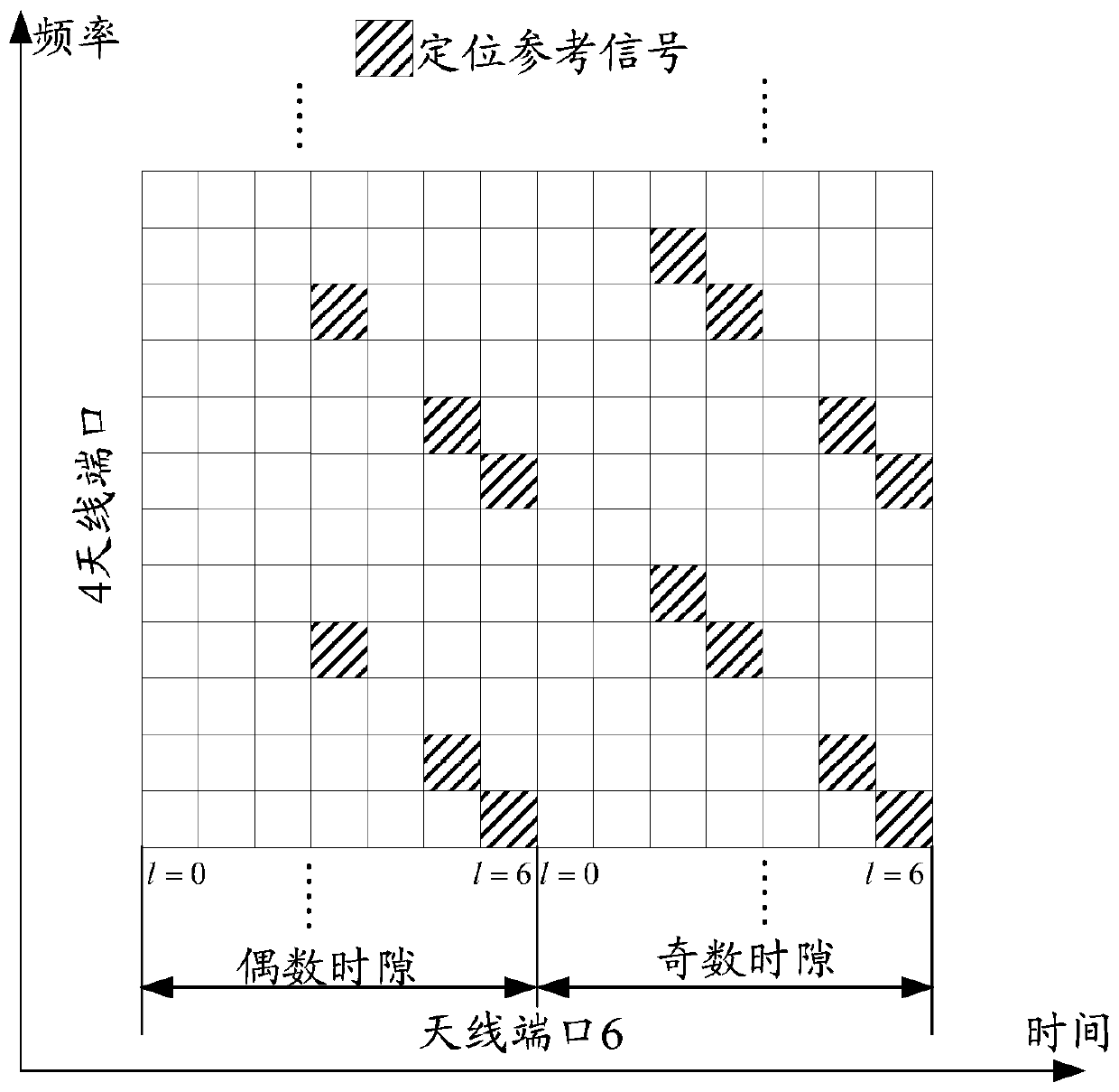
[0088] Example 2: Frequency domain density indicator comb-6, taking normal CP as an example

[0089] Such as Figure 6a As shown, the frequency domain density indication comb-6 in the resource configuration information configured by the network configuration, the frequency domain offset is 1, the number of symbols included is 6, the position of the first symbol is 3, and the lowest frequency domain position in the first symbol is 0.

[0090] Such as Figure 6b As shown, the frequency domain density indicator comb-6 in the resource configuration information configured by the network configuration, the frequency domain offset is 1, the number of symbols included is 10, the first symbol position is 3, and the lowest frequency domain position in the first symbol is 0.

[0091] Such as Figure 6c As shown, the frequency domain density indicator comb-6 in the resource configuration information configured by the network configuration, the frequency domain offset is 2, the number ...

example 3

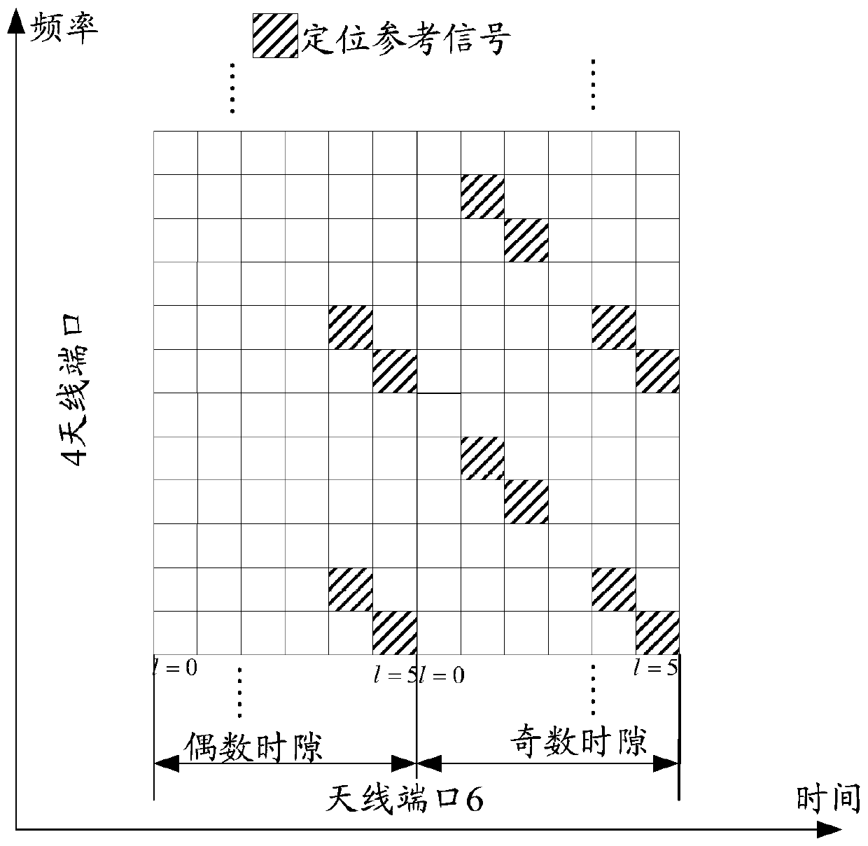
[0095] Example 3: Frequency domain density indicator comb-4, taking normal CP as an example

[0096] Such as Figure 7a As shown, the frequency domain density indicator comb-4 in the resource configuration information configured by the network configuration, the frequency domain offset is 1, the number of symbols included is 4, the first symbol position is 3, and the lowest frequency domain position in the first symbol is 0.

[0097] Such as Figure 7b As shown, the frequency domain density indicator comb-4 in the resource configuration information configured by the network configuration, the frequency domain offset is 1, the number of symbols included is 8, the first symbol position is 3, and the lowest frequency domain position in the first symbol is 0.

[0098] Such as Figure 7c As shown, the frequency domain density indicator comb-4 in the resource configuration information configured by the network configuration, the frequency domain offset is 2, the number of symbol...


PUM


Abstract

The invention discloses a positioning reference signal configuration method, network equipment and a terminal. The method comprises the following steps: sending resource configuration information of apositioning reference signal; sending a positioning reference signal according to a resource pattern indicated by the resource configuration information; wherein the resource configuration information comprises at least one parameter item, the value of the parameter item is one of at least two selectable values corresponding to the parameter item, and the resource pattern is related to the valueof the parameter item. According to the embodiment of the invention, the method comprises the steps: carrying out the processing, in the embodiment of the invention, the network equipment configures the resource configuration information of the positioning reference signal for the terminal, and the value of the parameter item in the resource configuration information is one selected from at leasttwo selectable values by the network equipment, so that the system can support configurable positioning reference signal resource allocation, more flexible resource configuration can be supported, andthe resource utilization rate is improved.

Description

technical field [0001] The present invention relates to the field of communication technologies, in particular to a positioning reference signal configuration method, network equipment and a terminal. Background technique [0002] A positioning reference signal (Positioning Reference Signal, PRS) is a reference signal (Reference Signal, RS) used for downlink positioning. The terminal measures the PRS sent from multiple cells (cells) or multiple transmission points, and after obtaining the Reference Signal Time Difference (RSTD) between multiple cells or transmission points, the terminal sends the measured RSTD information to The positioning server calculates and obtains the location of the terminal. [0003] In the Long Term Evolution (LTE) system, the PRS can be transmitted in the resource blocks of the downlink subframe configured for positioning reference signal transmission. The PRS has strong autocorrelation and orthogonality characteristics, and the signal During the...

Claims


Application Information

Patent Timeline
Patent Type & Authority Applications(China)
IPC IPC(8): H04L5/00H04W72/04H04L27/00
CPCH04L5/0048H04W72/0446H04W72/0453H04W4/02H04W64/00H04W72/23H04L5/005H04L5/0094H04L5/0023H04L5/0026H04L5/0007H04W72/51
Inventor 司晔孙鹏邬华明孙晓东
Owner VIVO MOBILE COMM CO LTD
Why Eureka
Try Eureka