

Large barrel automatic welding detection fixing device
An automatic welding and fixing device technology, applied in auxiliary devices, welding equipment, auxiliary welding equipment, etc., can solve problems such as pipe butt deviation, welding accuracy influence, and abnormal welding, so as to avoid poor welding, increase support, The effect of improving welding quality
- Summary
- Abstract
- Description
- Claims
- Application Information
AI Technical Summary
Problems solved by technology
Method used
Image

Examples
Embodiment Construction
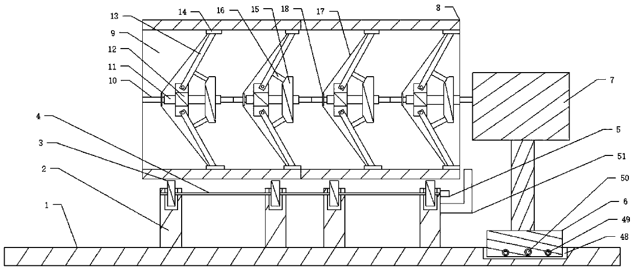
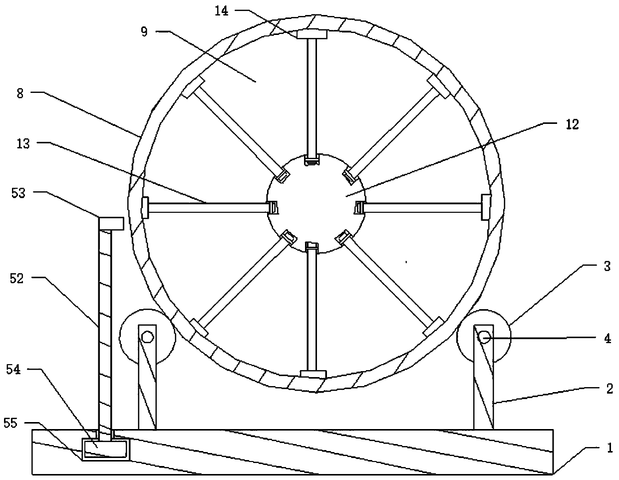
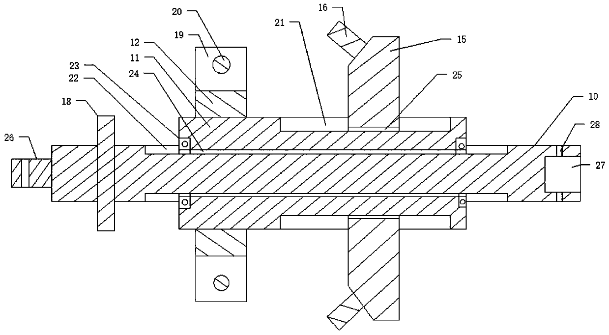
[0029] Such as Figure 1 to Figure 6As shown, a large-scale cylinder automatic welding detection and fixing device includes a support platform 1, and a row of support columns 2 are fixedly connected to both sides of the support platform 1, and a row of support columns 2 are arranged side by side. The first rotating shaft 4, the first rotating shaft 4 is respectively provided with a plurality of rotating rollers 3, the support column 2 on one side is provided with a first motor 5 that drives the first rotating shaft 4 to rotate, and the rotating rollers on both sides 3 is provided with a welding cylinder 8, the welding cylinder 8 is provided with a cylinder groove 9, and a sliding base 6 for lateral sliding is provided on the support platform 1, and a control module 7 is provided on the sliding base 6, so that The control module 7 is provided with a telescopic sliding shaft 36 that slides telescopically. The telescopic sliding shaft 36 is provided with a fourth rotating shaft 3...
PUM
 Abstract
Description
Claims
Application Information