Clamping base of assembled type cloth stretching frame on quilting machine
An assembly-type, quilting machine technology, applied in the field of quilting machines, can solve problems affecting the production efficiency of quilting machines, too many clips, long time-consuming clamping and disassembly of bedding, etc., to shorten replacement time, improve production efficiency, The effect of easy disassembly and installation
- Summary
- Abstract
- Description
- Claims
- Application Information
AI Technical Summary
Problems solved by technology
Method used
Image

Examples
Embodiment
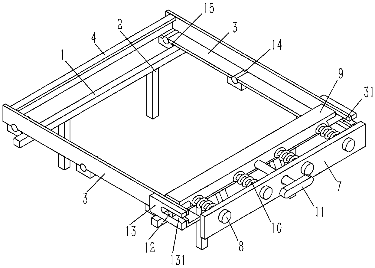
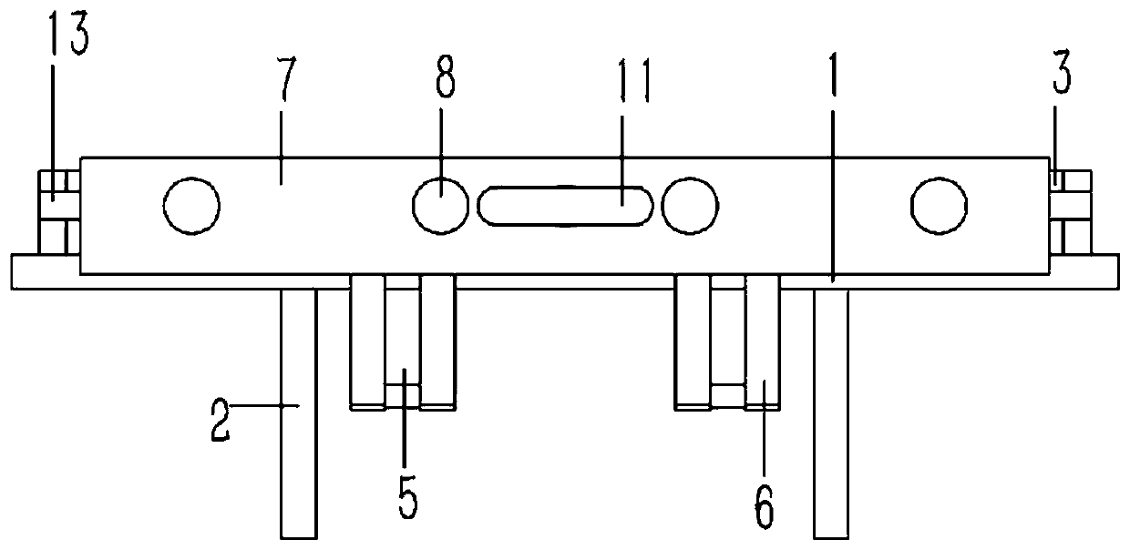
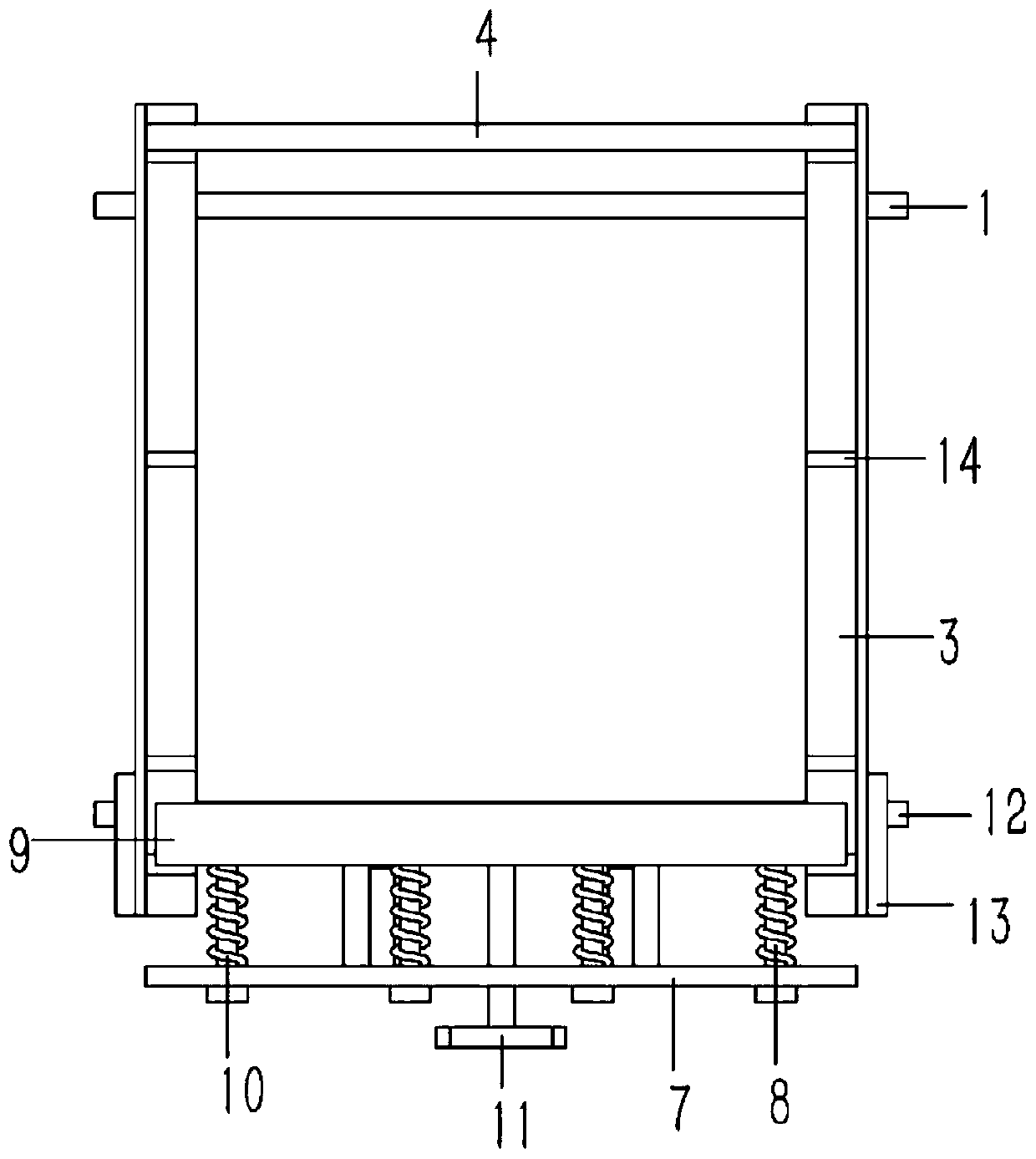
[0019] Example: see Figures 1 to 4 As shown, a clamping seat of an assembled stretcher on a quilting machine includes two front and rear beams 1, the lower end of the beam 1 is fixed with a column 2, and the two sides of the beam 1 are fixed with L-shaped side brackets 3. The rear end of the side bracket 3 is fixed with an L-shaped rear splint 4, and the front end of the side bracket 3 is provided with an L-shaped front splint 9; a number of inclined rear connecting rods 5 are fixed on the crossbeam 1 at the front end of the side bracket 3 , the lower end of the rear connecting rod 5 is hinged with an inclined front connecting rod 6 through the hinge shaft, and the upper end of the front connecting rod 6 is fixed on the vertical support plate 7, and several T-shaped guides are plugged on the support plate 7. The rod 8 and the guide rod 8 pass through the support plate 7 and are fixed on the front splint 9; the guide rod 8 is inserted with a compression spring 10, and the two ...
PUM
 Abstract
Description
Claims
Application Information