Novel multifunctional deceleration strip

A multi-functional, speed bump technology, applied in the traffic field, can solve the problem of single function of speed bumps and achieve the effect of improving road safety

Inactive Publication Date: 2020-06-16
雷新刚
View PDF6 Cites 10 Cited by
  • Summary
  • Abstract
  • Description
  • Claims
  • Application Information

AI Technical Summary

Problems solved by technology

[0005] The purpose of the present invention is to provide a new type of multi-functional speed bump with water sprinkling function to solve the problem that most of the above-mentioned traditional speed bumps have relatively single functions.

Method used


Image

  • Novel multifunctional deceleration strip
  • Novel multifunctional deceleration strip
  • Novel multifunctional deceleration strip

Examples


Embodiment 1

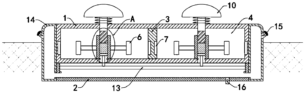
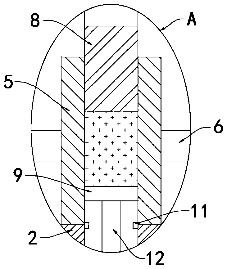
[0023] Such as Figure 1-2 As shown, a new type of multifunctional deceleration belt includes a frame body 1, the upper end of the frame body 1 is set higher than the ground, the lower end of the frame body 1 is fixedly connected with a water storage box 2, and the frame body 1 is provided with at least one vertical The partition plate 3 is provided, and the partition plate 3 is fixedly connected inside the frame body 1 and divides the frame body 1 into a plurality of deceleration chambers 4, and the lower bottom surface of each deceleration chamber 4 is rotatably connected with a vertically arranged fixed cylinder 5, The fixed cylinder 5 is rotationally connected with the decelerating chamber 4 through bearings, and a plurality of conductive strips 6 are fixedly connected to the peripheral side walls of the fixed cylinder 5 .

[0024] The side wall corresponding to the conductive strip 6 in the deceleration chamber 4 is fixedly embedded with a magnetic ring 7, the direction o...

Embodiment 2

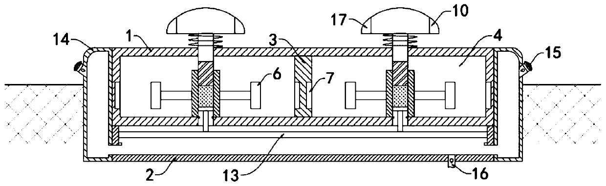
[0034] Such as image 3 As shown, the difference between this embodiment and Embodiment 1 lies in that: warning lights 17 are installed on the side walls of the plurality of speed bumps 10 , and the warning lights 17 are electrically connected to the conductive strips 6 .

[0035] In this embodiment, when the conductive strip 6 rotates with the fixed cylinder 5, it will cut the magnetic induction line of the magnetic ring 7, so that the warning light 17 is energized and illuminated. When the vehicle rolls on the deceleration strip 10 at a higher speed, the fixed cylinder 5 will The faster the conductive strip 6 is driven to rotate, the greater the induced current will be, and the brightness of the warning light 17 will be greater, which can play an obvious warning role.


PUM


Abstract

The invention belongs to the field of traffic, the invention relates to a deceleration strip, in particular to a novel multifunctional deceleration strip. Frame body, the lower end of the frame body is fixedly connected with a water storage box; at least one vertically-arranged partition plate is arranged in the frame body. The partition plates are fixedly connected into the frame body and dividethe frame body into a plurality of speed reduction cavities. The lower bottom surface of each deceleration cavity is rotatably connected with a vertically arranged fixed cylinder; a plurality of conductive strips are fixedly connected to the peripheral side wall of the fixed cylinder; a magnetic ring is fixedly embedded in the side wall, corresponding to the conductive strip, in the speed reduction cavity, the lower end of the fixed cylinder communicates with the water storage box, a threaded rod and a sliding plate are arranged in the fixed cylinder, electrorheological fluid electrically connected with the conductive strip is contained between the threaded rod and the sliding plate, and the upper end of the threaded rod extends out of the frame body and is fixedly connected with the speedreduction strip. The deceleration strip is provided with the water sprinkling mechanism, when a vehicle passes through the deceleration strip, water in the water supply box can be squeezed out of thedeceleration strip, water can be sprinkled to the road surface, dust in air can be settled, and the road can be cleaned.

Description

technical field [0001] The invention belongs to the field of transportation, and in particular relates to a novel multifunctional deceleration belt. Background technique [0002] In recent years, speed bumps have become very popular in urban traffic, especially in campuses. Due to the large flow of people, speed bumps can be seen everywhere. For pedestrians, the appearance of speed bumps is a boon, because it can force drivers to reduce their driving speed. Speed, to ensure the safety of passers-by. [0003] Most of the traditional speed bumps are made of hard rubber material, which slows down the passing vehicles by arching the road surface. However, when the vehicle passes at a reduced speed, it will still produce a strong sense of bumps, so there are often vehicles speeding up and slowing down. In order to reduce the duration of the bumps, it will not only fail to slow down the car, but also increase the safety hazards of road traffic. Moreover, for some roads at campus ...

Claims


Application Information

Patent Timeline
Patent Type & Authority Applications(China)
IPC IPC(8): E01F9/529E01H3/04
CPCE01H3/04E01F9/529
Inventor 雷新刚
Owner 雷新刚
Why Eureka
Try Eureka