Synchronizer apparatus for transmission

A synchronizer and transmission technology, applied in transmission, transmission control, gear transmission, etc., can solve problems such as poor shift feeling, reduce shifting shock and/or shock noise, and interrupt torque transmission reduced effect

Pending Publication Date: 2020-06-16
HYUNDAI MOTOR CO LTD +1
View PDF0 Cites 0 Cited by
  • Summary
  • Abstract
  • Description
  • Claims
  • Application Information

AI Technical Summary

Problems solved by technology

[0019] We have found that when the shift fork is moved quickly during the shifting operation, the sleeve 5 may collide with the stop of the clutch gear 9, causing impact noise and thus poor shifting feel

Method used


Image

  • Synchronizer apparatus for transmission
  • Synchronizer apparatus for transmission
  • Synchronizer apparatus for transmission

Examples


Embodiment Construction

[0073] The following description is merely exemplary in nature and is not intended to limit the invention, application or uses. It should be understood that throughout the drawings, corresponding reference numerals indicate like or corresponding parts and features.

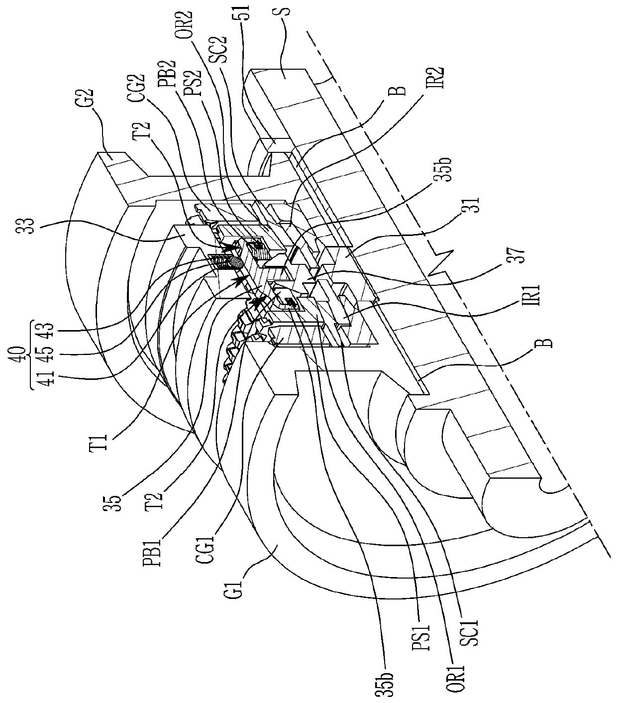
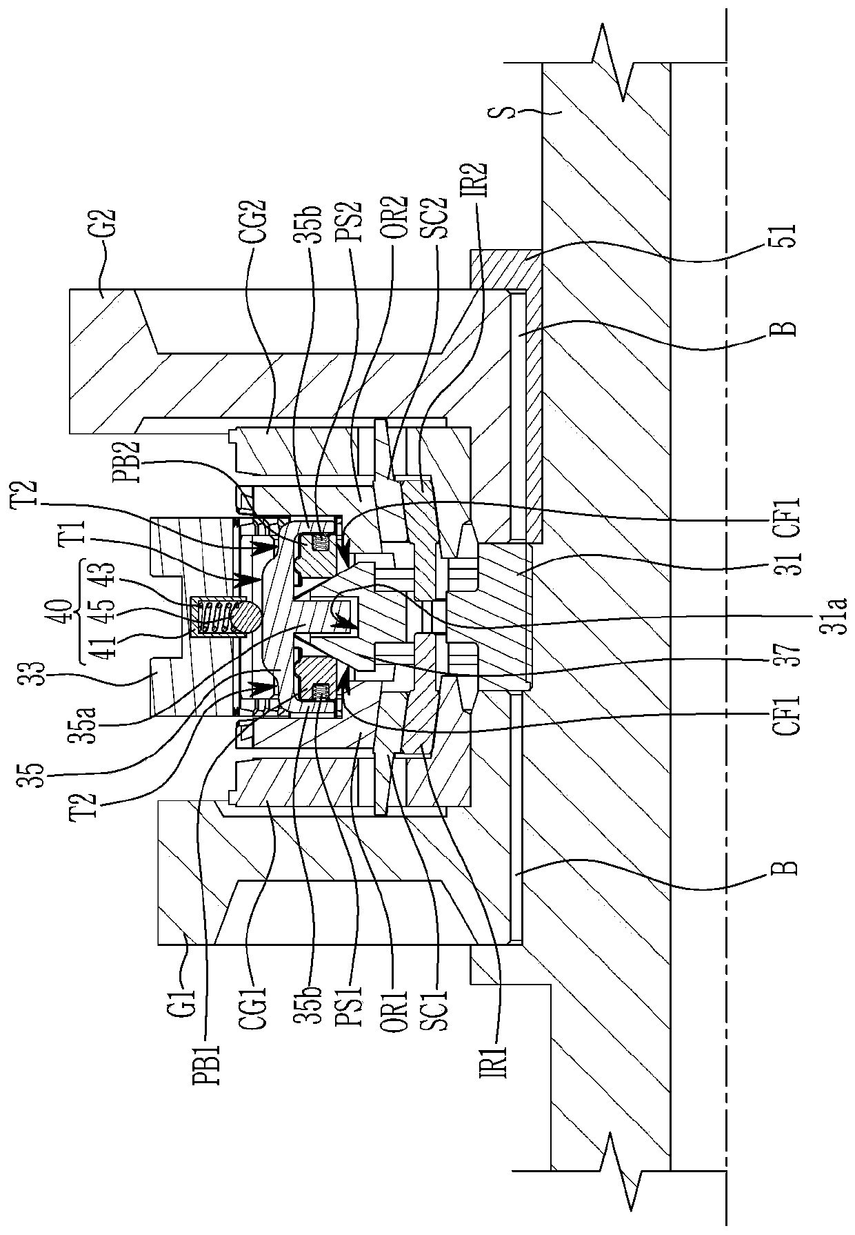
[0074] figure 2 is a sectional perspective view of a synchronizer device for a transmission according to an exemplary embodiment of the present invention. image 3 is a sectional view of a synchronizer device for a transmission according to an exemplary embodiment of the present invention.

[0075] refer to figure 2 and image 3 , the synchronizer device for the transmission is arranged between the first shifting gear G1 and the second shifting gear G2 installed on the output shaft S of the transmission, and selectively connects the first shifting gear G1 and the second shifting gear G1 The gear G2 is synchronously connected with the output shaft S.

[0076] This synchronizer device for a transmission compr...


PUM


Abstract

The invention provides a synchronizer apparatus for a transmission, which includes: first and second shifting gears rotatable on an output shaft; a hub spline-coupled with the output shaft and havinga slope portion having slanted surfaces; a sleeve spline-coupled with the hub; a key coupled with a recess of a slope portion; first and second clutch gears disposed between the hub and shifting gears; first and second outer rings and first and second inner rings disposed between the hub and clutch gears; first and second synchronizer cones disposed between the first inner and outer rings and thesecond inner and outer rings; a poppet ball unit disposed at the sleeve and contacting the key through a poppet ball; first and second push blocks disposed at the slanted surfaces; and first and second push springs inserted in spring holes formed at the push blocks to force push blocks to the slanted surfaces.

Description

[0001] Cross References to Related Applications [0002] This application claims priority and benefit from Korean Patent Application No. 10-2018-0157490 filed on December 7, 2018, the entire contents of which are incorporated herein by reference. technical field [0003] The invention relates to a synchronizer device for a transmission. Background technique [0004] The statements in this section merely provide background information related to the present disclosure and may not constitute prior art. [0005] A synchronizer device for a vehicle transmission is generally a device for synchronously coupling a shift gear (ie, a transmission gear) to an output shaft through operation of a shift fork. [0006] figure 1 is a cross-sectional view of a typical synchronizer device used in a transmission. [0007] refer to figure 1 , in a typical synchronizer device for a transmission, a hub 3 is spline-coupled with an output shaft 1, and a sleeve 5 is arranged on teeth on the out...

Claims


Application Information

Patent Timeline
Patent Type & Authority Applications(China)
IPC IPC(8): F16H3/12
CPCF16H3/12F16D23/06F16D2023/0618F16D2023/0681F16H2063/3093F16D2023/0637F16D23/0612F16H63/30
Inventor 金千玉申容旭孙宇哲鱼顺基张祐槙权纯星蔡民浩
Owner HYUNDAI MOTOR CO LTD
Why Eureka
Try Eureka