Laser obstacle clearing instrument collimating lens with automatic focusing function

A technology of automatic focus and obstacle removal device, which is applied in the field of laser obstacle removal device

Pending Publication Date: 2020-06-16
SHANGHAI XIBANG ELECTRIC
View PDF1 Cites 3 Cited by
  • Summary
  • Abstract
  • Description
  • Claims
  • Application Information

AI Technical Summary

Problems solved by technology

[0007] The purpose of the present invention is to provide a collimating lens of a laser obstacle removal device with an automatic focusing function, which mainly solves the technical problems existing in the manual focus mode of the existing laser obstacle removal device. The actual obstacle distance, adjust to the best focal length to get the best obstacle removal effect

Method used


Image

  • Laser obstacle clearing instrument collimating lens with automatic focusing function
  • Laser obstacle clearing instrument collimating lens with automatic focusing function
  • Laser obstacle clearing instrument collimating lens with automatic focusing function

Examples


Embodiment Construction

[0026] The following will clearly and completely describe the technical solutions in the embodiments of the present invention with reference to the accompanying drawings in the embodiments of the present invention. Obviously, the described embodiments are only some, not all, embodiments of the present invention.

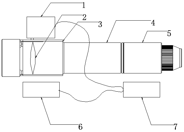
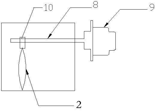
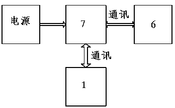
[0027] like figure 1 As shown, it is a structural schematic diagram of a collimating lens of a laser obstacle removal device with an automatic focusing function according to the present invention. As shown in the figure: it consists of 7 parts: electric focusing device 1, focusing lens 2, focusing lens bin 3, lens barrel 4, QBH laser collimation head 5, distance measuring module 6, and budget processing unit 7. The specific structure is: a focusing lens 2 driven by the electric focusing device 1 to move back and forth in the focusing lens compartment 3 is arranged in the focusing lens compartment 3; the rear end of the focusing lens compartment 3 is connected to the ...


PUM


Abstract

The invention relates to a laser obstacle clearing instrument collimating lens with an automatic focusing function. The collimating lens comprises a focusing lens bin, wherein a focusing lens driven by an electric focusing device to move back and forth in the focusing lens bin is arranged in the focusing lens bin; the rear end of the focusing lens bin is connected with the front end of the lens cone, and the QBH laser collimating head is installed at the rear end of the lens cone; the electric focusing device is connected and controlled by an operation processing unit, and the operation processing unit is further connected with a distance measuring module used for measuring the distance between an obstacle needing to be removed and the focusing lens. In the actual use process, a user adjusts the optimal focal length according to the distance of the actual obstacle so as to obtain the optimal obstacle removing effect.

Description

technical field [0001] The invention relates to a laser obstacle removal device, in particular to a collimating lens of a laser obstacle removal device with an automatic focusing function. Background technique [0002] Overhead high-voltage and low-voltage transmission lines can be seen everywhere in daily life. Plastic films, kite lines, and balloon lines are often entangled on the transmission lines, threatening the safety of power supply. [0003] At present, manual cleaning is usually performed under the condition of power supply, and workers work at high altitude with electricity, which has a high risk, and the cleaning time is long and the effect is not ideal. There are also controllable robots or automated devices to remove obstacles, but these devices have complex structures, high failure rates, and the need for multiple people to cooperate and cooperate. Before use, the devices need to be hung on overhead transmission lines. Hidden dangers still exist, and it takes...

Claims


Application Information

Patent Timeline
Patent Type & Authority Applications(China)
IPC IPC(8): G02B7/04G02B7/28G02B19/00H02G1/02B23K26/36B23K26/046
CPCG02B7/04G02B7/28G02B19/0014H02G1/02B23K26/36B23K26/046
Inventor 杨浩明王淳文程
Owner SHANGHAI XIBANG ELECTRIC
Why Eureka
Try Eureka