
Electric power identification pile

A technology for marking piles and electric power, applied in the field of power marking piles, can solve the problems of high cost of finding suspects, cable safety threats, adverse effects on residents' life and work electricity consumption, etc., so as to avoid property loss and hidden safety hazards and enhance self-protection. Effect, deterrent effect of illegal and criminal behavior

Active Publication Date: 2020-06-16
SHENZHEN POWER SUPPLY BUREAU
View PDF16 Cites 1 Cited by
  • Summary
  • Abstract
  • Description
  • Claims
  • Application Information

AI Technical Summary

Problems solved by technology

If the marking pile is artificially damaged, not only the safety of the cables under the marking pile will be threatened, it may lead to the paralysis of the power supply system within the power supply range of the cable, which will adversely affect the residents' life and work electricity consumption, and the damaged cable will have leakage current Possibly, a safety hazard to nearby pedestrians
[0003] The traditional electric power sign post consists of two parts, one is the pile body, the other is the warning slogan, and usually a striking color is painted on the outside of the electric sign post, although the traditional electric sign post is already very obvious to the public. , but in the actual situation, there are still a large number of cases where the power marker piles are intentionally or unintentionally destroyed. Moreover, due to the difficulty of investigation and evidence collection, the cost of finding suspects is high, and it is usually nothing. effective protection

Method used


Image

  • Electric power identification pile
  • Electric power identification pile
  • Electric power identification pile

Examples


Embodiment Construction

[0036] In order to facilitate the understanding of the present application, the present application will be described more fully below with reference to the relevant drawings. Preferred embodiments of the application are shown in the accompanying drawings. However, the present application can be embodied in many different forms and is not limited to the embodiments described herein. On the contrary, the purpose of providing these embodiments is to make the understanding of the disclosure of the application more thorough and comprehensive.

[0037] Unless otherwise defined, all technical and scientific terms used herein have the same meaning as commonly understood by one of ordinary skill in the technical field to which this application belongs. The terms used herein in the specification of the application are only for the purpose of describing specific embodiments, and are not intended to limit the application. As used herein, the term "and / or" includes any and all combinati...


PUM


Abstract

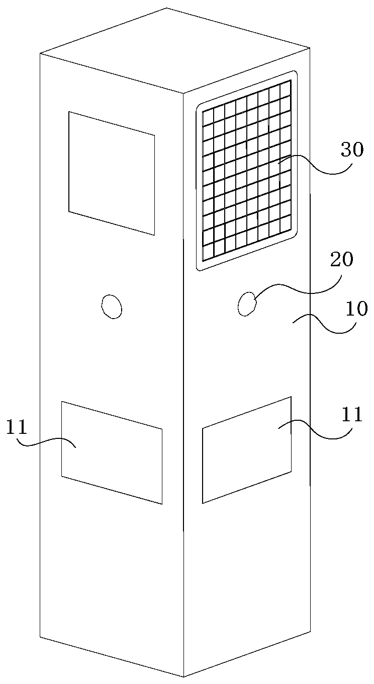
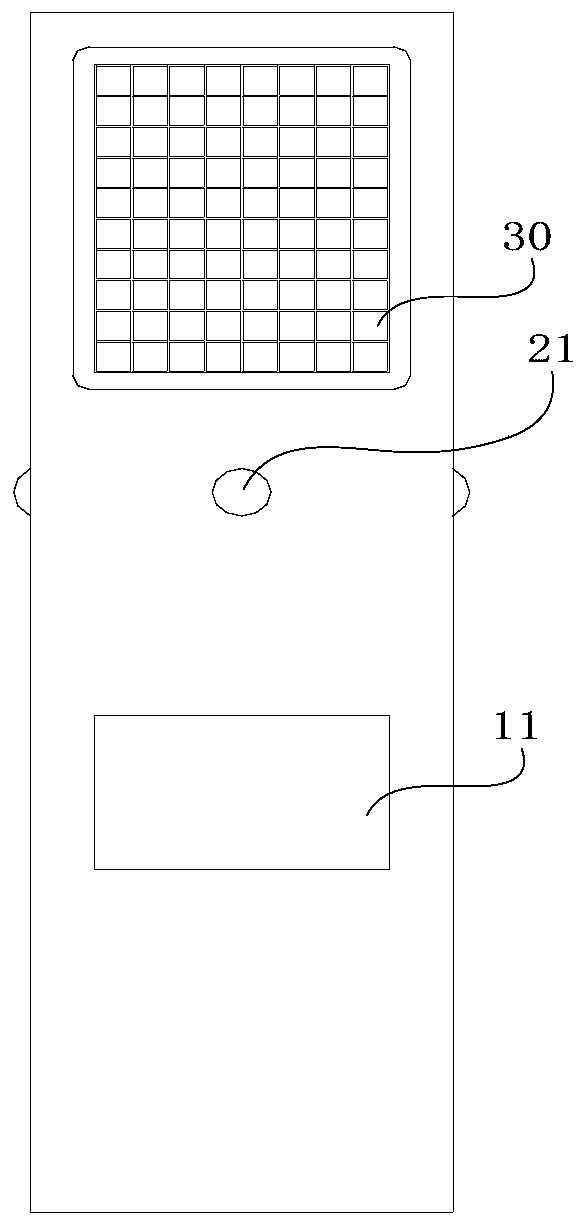
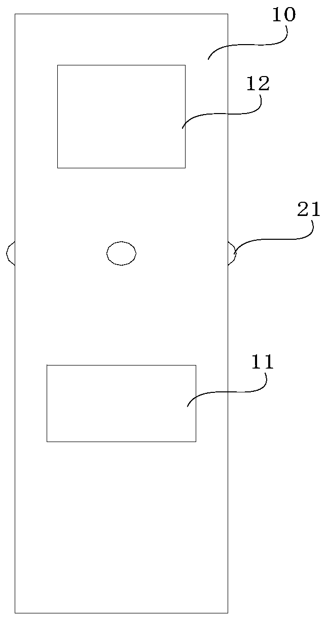
The invention relates to the technical field of electric power transmission, in particular to an electric power identification pile which comprises: a pile body in a hollow column shape, wherein an electric power identification is arranged on the outer surface of the pile body; a monitoring device arranged on the pile body and used for acquiring video and / or image information around the pile body;and a control circuit which is arranged on the pile body, is connected with the monitoring device and is used for receiving the video and / or the image information and sending the video and / or the image information to a server. The monitoring device transmits the acquired video and / or image information to a server through the control circuit; video and / or image information in the surrounding environment of the electric power identification pile can be remotely acquired through the server. Evidence information of damaging the cable can be obtained, investigation and evidence obtaining difficulty is reduced, safety management in electric power operation and maintenance is promoted, property loss and potential safety hazards are avoided, and meanwhile a frightening effect on illegal criminalbehaviors of maliciously damaging electric power facilities can be achieved.

Description

technical field [0001] The present application relates to the technical field of power transmission, in particular to a power identification post. Background technique [0002] Electric power marking pile is a kind of marking pile product used in electric power engineering projects. It is generally suitable for engineering projects such as cable trenches, underground cables, and buried cables to serve as warnings and signs. The use of cable identification stakes can indicate the existence of underground cable pipelines, and can also avoid damage to underground pipelines or casualties during engineering construction. If the marking pile is artificially damaged, not only the safety of the cables under the marking pile will be threatened, it may lead to the paralysis of the power supply system within the power supply range of the cable, which will adversely affect the residents' life and work electricity consumption, and the damaged cable will have leakage current Possibly, it...

Claims


Application Information

Patent Timeline
IPC IPC(8): H04N7/18G08B13/196G08B7/06G08B13/12
CPCG08B7/06G08B13/12G08B13/196H04N7/181
Inventor 成健罗智奕胡力广詹威鹏陈腾彪吴彦志陈显黎玉强周碧波具章平王晨阳冯小蔚梁艳菊胡小燕
Owner SHENZHEN POWER SUPPLY BUREAU
Learn More