
Vacuum system and warning method thereof

a vacuum system and vacuum technology, applied in the field of vacuum systems, can solve the problems of high labor cost, abnormal situations of devices that cannot be reacted to and resolved dynamically, production yield damage, etc., and achieve the effect of saving costs and improving the warning function of the traditional vacuum system

Inactive Publication Date: 2007-04-19
UNITED MICROELECTRONICS CORP
View PDF7 Cites 0 Cited by
  • Summary
  • Abstract
  • Description
  • Claims
  • Application Information

AI Technical Summary

Benefits of technology

[0006] In view of these limitations, one object of the present invention is to provide a vacuum system suitable for a semiconductor process to improve the warning function of the traditional vacuum system and save costs.
[0015] According to one embodiment of the present invention, said terminating signal can stop the operation of all of the devices in order to terminate the vacuum system.
[0021] Based on the above descriptions, the vacuum system of the present invention utilizes a warning / control unit and sensors to receive the sensing values obtained by the sensors to determine whether the devices of the vacuum system operate normally, so that operation of the vacuum system can be dynamically monitored, providing an effective warning and controlling system. In addition, by utilizing the warning method for a vacuum system according to the present invention, the cost of controlling and managing the vacuum system can be reduced.

Problems solved by technology

During a semiconductor process, control and management of vacuum conditions for the devices or chambers of the vacuum system are required to prevent the silicon wafer from being contaminated and thereby the production yield damaged.
Yet, since appropriate warnings for the traditional vacuum system rely on manpower to perform regular checking, not only labor cost required is high but abnormal situations of devices cannot be reacted to and resolved dynamically.
Hence, in terms of warning functions, the traditional vacuum system is insufficient and uneconomical.

Method used


Image

  • Vacuum system and warning method thereof
  • Vacuum system and warning method thereof
  • Vacuum system and warning method thereof

Examples


Embodiment Construction

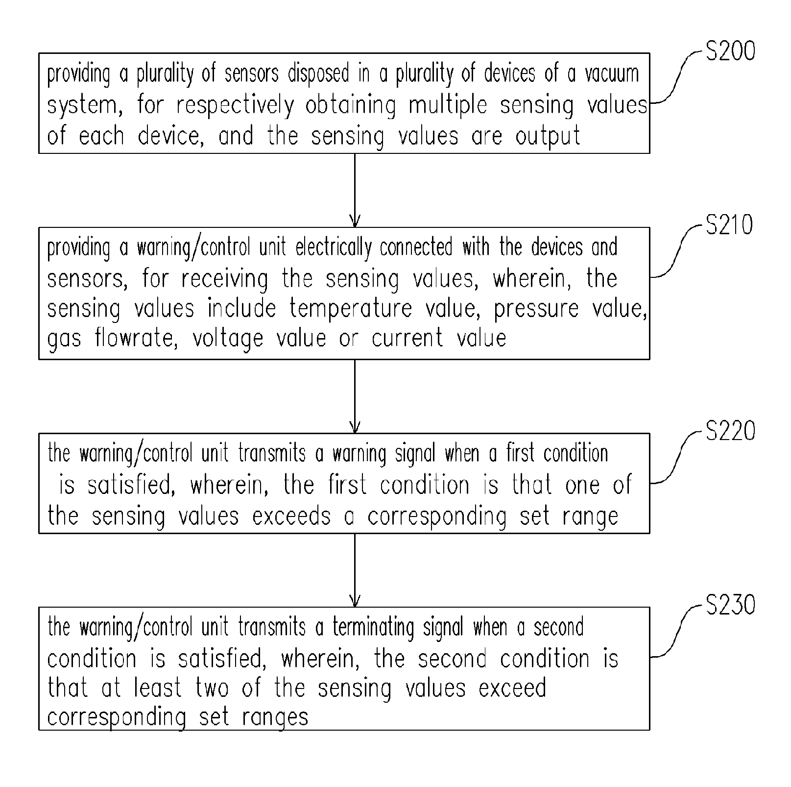
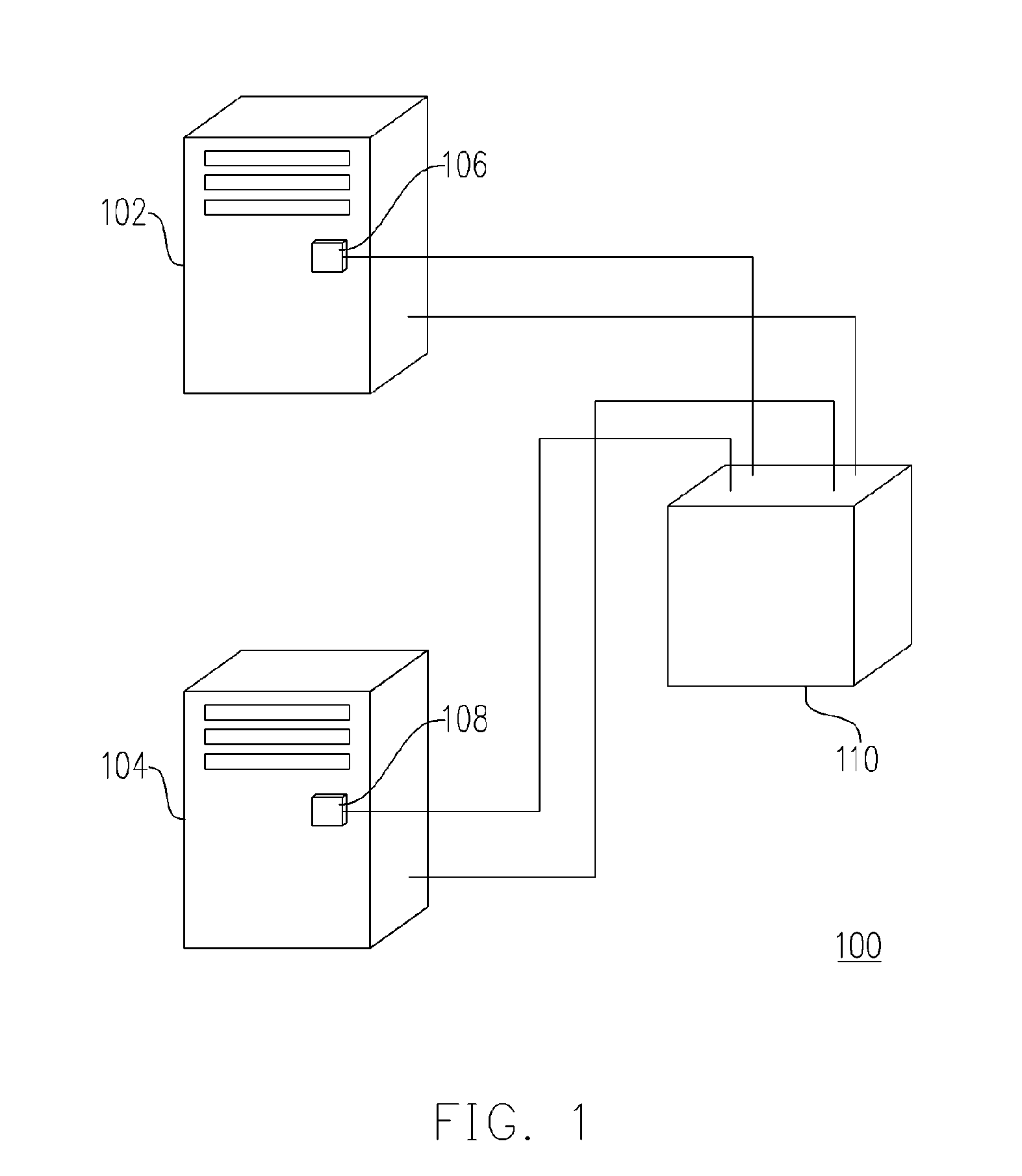
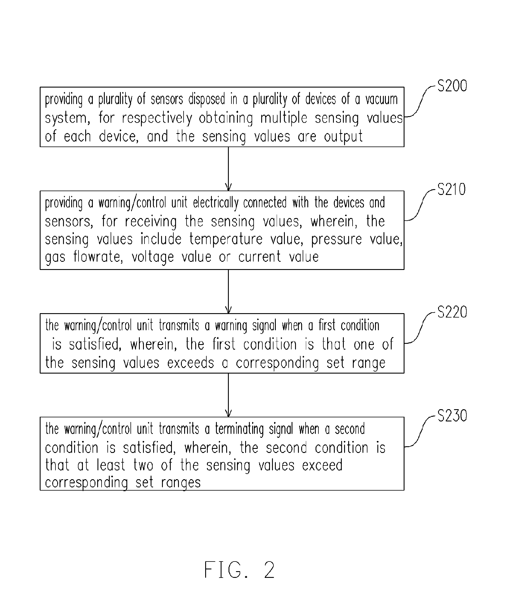
[0026]FIG. 1 schematically shows the vacuum system according to one embodiment of the present invention. In FIG. 1, the vacuum system 100 of the present embodiment is utilized to provide the gaseous ambience required to perform a semiconductor process. The semiconductor process can be an etching process, an exposure process, a deposition process or an ion implantation. The vacuum system 100, for example, comprises a first device 102, a second device 104, a first sensor 106, a second sensor 108 and a warning / control unit 110, wherein the first sensor 106 and the second sensor 108 are respectively disposed in the first device 102 and the second device 104, and they are electrically connected with the warning / control unit 110 respectively. The first sensor 106 and the second sensor 108 are utilized to perform the sensing of the operating state of the first device 102 and the second device 104, and to obtain and output the sensing values. The warning / control unit 110, which is electrica...


PUM


Abstract

A vacuum system suitable for a semiconductor process is provided. The vacuum system includes a plurality of devices, a plurality of sensors and a warning / control unit. The sensors are respectively disposed in these devices for performing sensing and they output a plurality of sensing values. The warning / control unit is electrically connected both with the devices and the sensors, and receives the sensing values output from the sensors. Wherein, the warning / control unit transmits a warning signal when a first condition is satisfied; otherwise, it transmits a terminating signal when a second condition is satisfied.

Description

BACKGROUND OF THE INVENTION [0001] 1. Field of Invention [0002] The present invention relates to a vacuum system. More particularly, it relates to a vacuum system having a warning capability. [0003] 2. Description of Related Art [0004] With the rapid development of the semiconductor industries and electronic techniques in recent years, electronic products having more powerful and superior functions are constantly being manufactured. In general, certain semiconductor processes including thin film deposition, etching, ion implantation and lithography, are performed to provide the semiconductor materials with specific electrical characteristics. The devices for performing the semiconductor processes usually need to be operated under suitable gas pressure, which is maintained by a vacuum system. In other words, the vacuum system is used to supply an ambience with a high vacuum state (i.e. low gas pressure). Accordingly, the semiconductor processes can be performed under the specific gas...

Claims


Application Information

Patent Timeline
Patent Type & Authority Applications(United States)
IPC IPC(8): G08B19/00F27D7/06G08G1/16G08B21/00
CPCF27D7/06H01L21/67253
Inventor HSU, HUNG-HUANG
Owner UNITED MICROELECTRONICS CORP
Learn More