Supercharge Your Innovation With Domain-Expert AI Agents!

Workpiece positioning device

A technology for positioning devices and workpieces, which is applied to positioning devices, metal processing machinery parts, manufacturing tools, etc., can solve the problems of low workpiece positioning efficiency, and achieve the effects of high positioning efficiency, simple setting operation, and improved positioning efficiency.

Pending Publication Date: 2020-06-19
浙江海德曼智能装备股份有限公司
View PDF0 Cites 0 Cited by
  • Summary
  • Abstract
  • Description
  • Claims
  • Application Information

AI Technical Summary

Problems solved by technology

[0004] The purpose of the present invention is to address the above problems in the prior art, and propose a workpiece positioning device, which solves the problem of low positioning efficiency when the existing workpiece is clamped

Method used


Image

  • Workpiece positioning device
  • Workpiece positioning device
  • Workpiece positioning device

Examples


Embodiment Construction

[0033] The following are specific embodiments of the present invention and in conjunction with the accompanying drawings, the technical solutions of the present invention are further described, but the present invention is not limited to these embodiments.

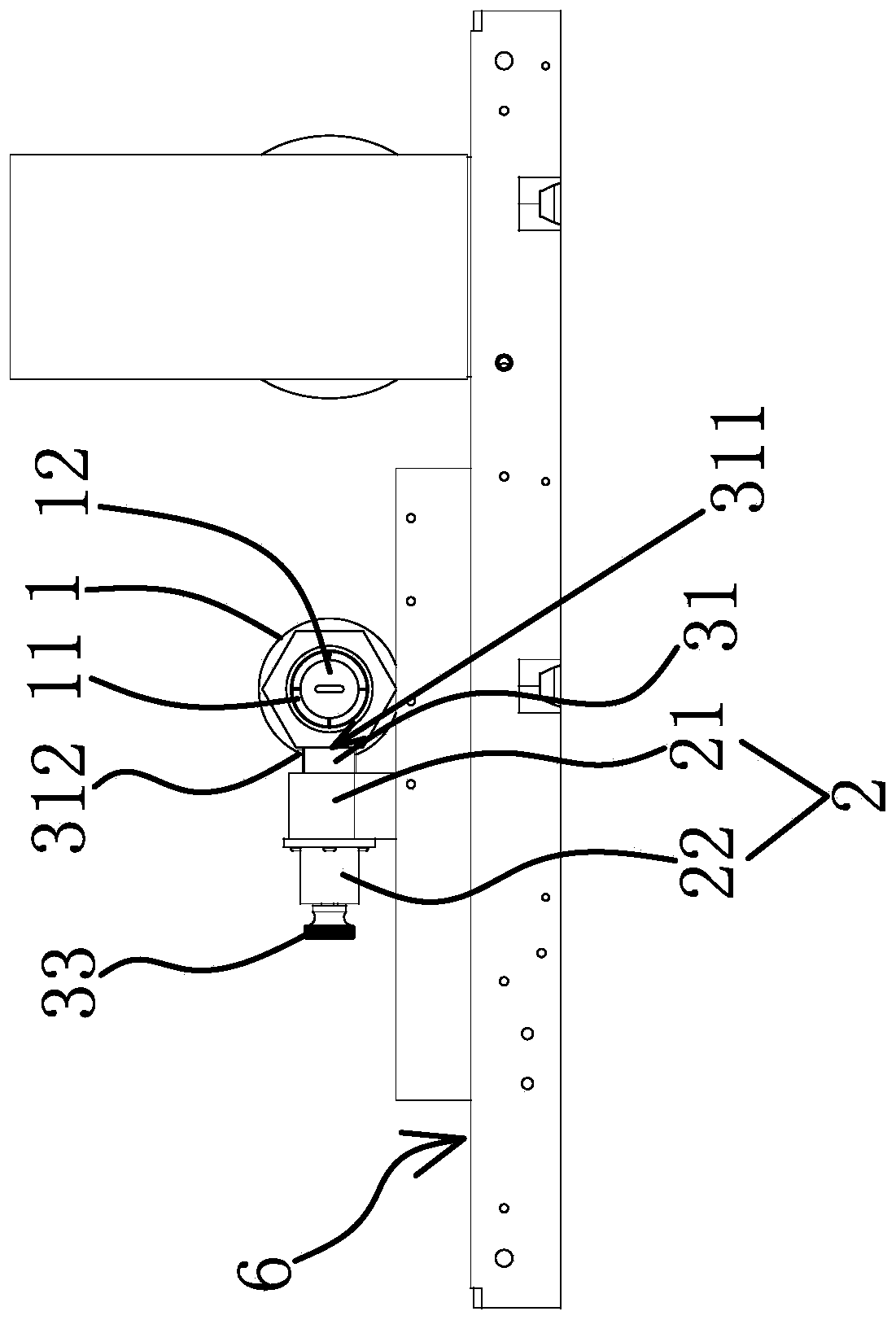
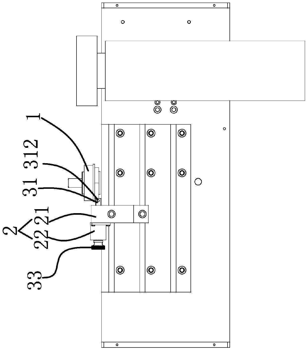
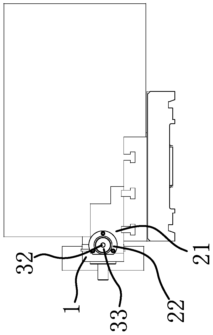
[0034] Such as Image 6 with Figure 7The shown workpiece positioning device includes a cylindrical internal expansion fixture 1, the internal expansion fixture 1 includes a columnar pusher 12 and a ring-shaped collar 13, and the right end of the collar 13 has four clamping parts 11 and the clamping portion 11 and the collar 13 are integrally constructed and made of metal materials. The four clamping parts 11 are arc-shaped, and the four clamping parts 11 are distributed in a circular shape around the axis of the collar 13. The pusher 12 is inserted in the collar 13 and the right end of the pusher 12 is located at the four Inside the clamping part 11, the inner walls of the four clamping parts 11 all have an inclined act...


PUM


Abstract

The invention provides a workpiece positioning device, and belongs to the technical field of positioning clamps. According to the workpiece positioning device, the problem that during current clampingof a workpiece, the positioning efficiency is low is solved. The positioning device comprises a cylindrical internal expansion clamp, a clamping part capable of being pushed out is arranged on the outer side wall of the internal expansion clamp, the positioning device comprises a shell with an inner hole and a positioning piece arranged in the shell, an elastic piece is further arranged in the shell, the positioning piece can stretch out from the front end of the shell under the elastic force effect of the elastic piece and get close to the internal expansion clamp, the inner wall of the shell can guide horizontal moving of the positioning piece, and the tip of the front end of the positioning piece is provided with a positioning face abutting against the workpiece. The positioning devicehas the advantage of improving the positioning efficiency greatly.

Description

technical field [0001] The invention belongs to the technical field of positioning fixtures, and relates to a positioning device, in particular to a workpiece positioning device. Background technique [0002] When using a lathe to cut workpieces, it is often encountered a class of blank workpieces with multiple blank surfaces such as two sides, four sides, and six sides, and each blank surface needs to be cut to meet production and processing requirements. Usually, the cutting process of this kind of workpiece is to set it on the fixture, the fixture is tensioned, and then the surface to be processed is accurately positioned, and then the positioned surface is cut by the tool, and the workpiece is replaced after processing. It needs to be repositioned every time. The difficulty in processing lies in how to quickly and accurately locate the workpiece so that it meets our processing requirements. [0003] The common method of workpiece positioning is to measure the offset dis...

Claims


Application Information

Patent Timeline
IPC IPC(8): B23Q3/18
CPCB23Q3/18
Inventor 孙乃金虞森洪高兆春赵伟
Owner 浙江海德曼智能装备股份有限公司
Features
  • R&D
  • Intellectual Property
  • Life Sciences
  • Materials
  • Tech Scout
  • Unparalleled Data Quality
  • Higher Quality Content
  • 60% Fewer Hallucinations
Learn More