Steel pipe rod safety placement device for steel plate rolling machine

A technology for steel pipe rods and steel plate coils, which is applied in the field of safe placement devices for steel pipe rods used in steel plate rolling machines, which can solve problems such as the danger of steel pipe rods rolling down, and achieve the effects of saving floor space, reducing width, and providing safety

Active Publication Date: 2022-04-19
重庆市荣昌区永世光电设备有限公司
View PDF13 Cites 0 Cited by
  • Summary
  • Abstract
  • Description
  • Claims
  • Application Information

AI Technical Summary

Problems solved by technology

[0005] The present invention intends to provide a safe placement device for steel pipe rods used in steel plate rolling machines to solve the problem in the prior art that steel pipe rods are stacked on the support frame and there is a dangerous situation of steel pipe rods rolling off

Method used


Image

  • Steel pipe rod safety placement device for steel plate rolling machine
  • Steel pipe rod safety placement device for steel plate rolling machine
  • Steel pipe rod safety placement device for steel plate rolling machine

Examples


Embodiment 1

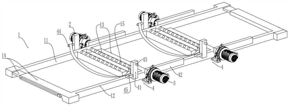
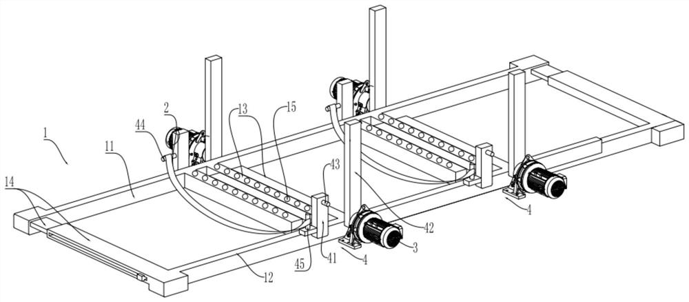
[0033] Embodiment one is basically as attached figure 1 and figure 2 Shown:

[0034] Steel pipe rod safety device for steel plate rolling machine, including support frame 1, two suspenders 2 and four motors 3, support frame 1 includes fixed bracket 11 and mobile bracket 12, and fixed bracket 11 and mobile bracket 12 include middle support Rod 13 and end strut 14, the end strut 14 of movable support 12 is horizontally slidably connected on the end strut 14 of fixed support 11, the upper surface of all intermediate struts 13 is parallel, the intermediate strut of movable support 12 13 and the middle struts 13 of the fixed bracket 11 are arranged in a staggered manner.

[0035] The upper surface of each middle support rod 13 of the fixed bracket 11 is rollingly connected with a ball 15, and adjacent balls 15 can be offset against the same steel pipe rod.

[0036] The bottom of the middle pole 13 of the mobile support 12 is provided with rollers in contact with the ground to f...

Embodiment 2

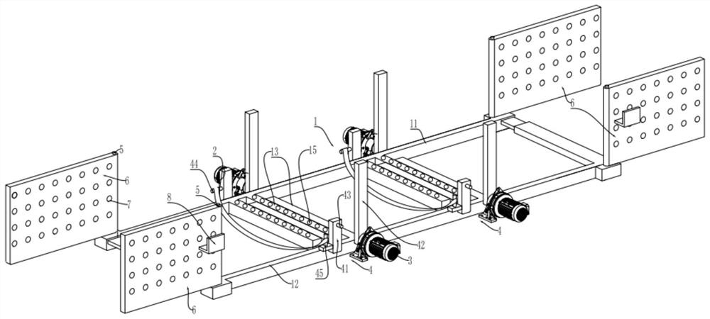
[0046] combine image 3 and Figure 4 , the second embodiment has been improved on the basis of the first embodiment as follows: the ends of the mobile support 12 and the fixed support 11 are welded with end columns 5, the end columns 5 are cylindrical, and the end columns 5 are rotatably connected with Coaming plate 6, coaming plate 6 can rotate 360° around the end column 5, several ventilation holes 7 are opened on the coaming plate 6, L-shaped support plate 8 is welded on the coaming plate 6, adjacent mobile bracket 12 and fixed bracket The coaming plate 6 of 11 is connected with the connecting plate 9 that two coaming plates 6 are connected, and the connecting plate 9 can be placed on the adjacent support plate 8 at the same time, and the connecting plate 9 adopts a telescopic tube that can be elongated and shortened.

[0047] The specific implementation process is as follows:

[0048] After the steel pipe pole is placed, the coaming plate 6 can be rotated so that the co...


PUM


Abstract

The invention relates to the technical field of storage equipment, and specifically discloses a safety device for placing steel pipe rods for a steel plate rolling machine, including a support frame, on which there are baffle groups. The number of baffle groups is at least two, and each group of baffle groups Both include two baffles 1 and 2 baffles, and the two baffles in the same baffle group are symmetrically arranged along the support frame; they also include a sling, which can be fixedly connected to the baffle 1; the baffle 2 is rotatably connected On the supporting frame, the rotation plane of the second baffle is a vertical plane, and the height of the second baffle after rotation is higher than that of the first baffle. This solution is used to solve the problem in the prior art that the steel pipe rods are stacked on the support frame and there is a dangerous situation of the steel pipe rods rolling down.

Description

technical field [0001] The invention relates to the technical field of storage equipment, in particular to a safety device for placing steel pipe rods for steel plate rolling machines. Background technique [0002] The steel pipe pole is obtained by curling the flat steel plate by a steel plate rolling machine. The steel pipe pole is tubular after forming. The steel pipe pole is generally used as an overhead pole in electric power transportation. The steel pipe pole is better than the traditional one because of its mechanical properties and safety performance. Concrete poles have been widely used in modern cities. [0003] After the steel pipe poles are formed, they are first stacked in the factory warehouse. When the steel pipe poles need to be pulled to the site to make overhead poles, the subsequent processing will be carried out. At present, the storage of steel pipe poles is generally to place the steel pipe poles on the support frame. The support frame enables the ste...

Claims


Application Information

Patent Timeline
Patent Type & Authority Patents(China)
IPC IPC(8): B65D61/00B65D85/20B65D85/62
CPCB65D61/00B65D85/20B65D85/62
Inventor 赵长刚
Owner 重庆市荣昌区永世光电设备有限公司
Why Eureka
Try Eureka