Rotary drilling rig anti-inclining elevator

A technology of rotary drilling rigs and lifters, which is applied to drill pipes, drill pipes, drilling equipment, etc., and can solve problems such as potential safety hazards, isolation rotation failure, and broken strength

Pending Publication Date: 2020-06-19
JIANGSU VOCATIONAL INST OF ARCHITECTURAL TECH
View PDF0 Cites 0 Cited by
  • Summary
  • Abstract
  • Description
  • Claims
  • Application Information

AI Technical Summary

Problems solved by technology

In order to realize the above two functions of the lifter, the vertical state between the lifter and the drill pipe connecting plate should be kept when the rotary drilling rig is drilling; if the lifter is inclined relative to the drill pipe connecting plate, especially when lifting When the upper joint of the guider leans against the inner wall of the outer section of the drill pipe, the upper and lower joints of the guider rotate together with the drill pipe, and the isolation rotation function fails. When the rotary drilling rig is drilling, the drill pipe will drive the steel wire rope to rotate together, causing the wire rope " "Strengthening" or "breaking strength", the wire rope is easy to damage
However, in actual operation, it often happens that the lowering length of the steel wire rope is longer than the actual required lowering length, causing the lifter to rotate and tilt around the pin axis of the drill pipe connecting plate and lean against the inner wall of the outer drill pipe, resulting in isolated rotation Functional failure, resulting in safety hazards

Method used


Image

  • Rotary drilling rig anti-inclining elevator
  • Rotary drilling rig anti-inclining elevator
  • Rotary drilling rig anti-inclining elevator

Examples


Embodiment Construction

[0021] The technical solutions in the embodiments of the present invention will be clearly and completely described below in conjunction with the accompanying drawings. Obviously, the described embodiments are only some, not all, embodiments of the present invention. The following description of at least one exemplary embodiment is merely illustrative in nature and in no way taken as limiting the invention, its application or uses. Based on the embodiments of the present invention, all other embodiments obtained by persons of ordinary skill in the art without creative work fall within the protection scope of the present invention.

[0022] Techniques, methods and devices known to those skilled in the art may not be discussed in detail, but where appropriate, such techniques, methods and devices should be considered part of the Authorized Description.

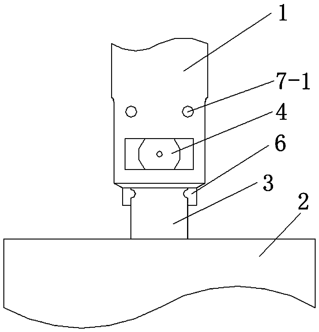
[0023] Such as figure 1 The anti-tilt lifting device of a rotary drilling rig shown includes a lower joint 1 of the lifting d...


PUM


Abstract

The invention discloses a rotary drilling rig anti-inclining elevator, and belongs to the technical field of rotary drilling rigs. The rotary drilling rig anti-inclining elevator comprises an elevatorlower joint, and the middle of the lower end of the elevator lower joint is provided with a connection groove; the upper end of a drill rod is provided with a connection plate which is inserted intothe connection groove and hinged to the elevator lower joint through a hinged shaft; the interior of the connection groove is provided with two anti-inclining limiting plates and a locking device which is matched with the anti-inclining limiting plates to prevent the connection plate from rotating; and the anti-inclining limiting plates are symmetrically arranged on the two sides, having rotationtrend, of the connection plate, one ends of the anti-inclining limiting plates are hinged to the upper portion of the connection groove, and the other end of the anti-inclining limiting plates are closely attached to the side of the connection plate. According to the rotary drilling rig anti-inclining elevator, the phenomenon that the release length of a steel wire rope is too large, and an elevator inclines can be prevented, it is ensured that the steel wire rope does not rotate along with a rill rod, and potential safety hazards are eliminated.

Description

technical field [0001] The invention relates to a lifter for a rotary drilling rig, belonging to the technical field of rotary drilling rigs. Background technique [0002] Rotary drilling rig is a kind of construction machinery commonly used in building foundation construction, and it is mainly used for the construction of building pile foundation. The lifter is an important part between the drill pipe and the wire rope of the rotary drilling rig. The upper joint is connected with the wire rope, and the lower joint is connected with the drill pipe. During normal operation, the wire rope, the lifter and the drill pipe are in a straight line. The upper and lower joints of the lifter can be relatively rotated. There are two main functions of the lifter. One is to transmit the lifting force of the wire rope to lift or lower the drill pipe; And prolong the service life of the wire rope. In order to realize the above two functions of the lifter, the vertical state between the l...

Claims


Application Information

Patent Timeline
IPC IPC(8): E21B19/02
CPCE21B19/02
Inventor 陈以田
Owner JIANGSU VOCATIONAL INST OF ARCHITECTURAL TECH
Why Eureka
Try Eureka