
Convenient-to-mount hydraulic pipeline repair device

A pipeline and water conservancy technology, which is applied in the field of water conservancy pipeline repairing devices, can solve the problems of wasting water resources, affecting pipelines, and harming the health of workers, and achieves the effects of low impact pressure, easy installation work, and reduced strength.

Active Publication Date: 2020-06-19
宁夏银江建设工程有限公司
View PDF9 Cites 4 Cited by
  • Summary
  • Abstract
  • Description
  • Claims
  • Application Information

AI Technical Summary

Problems solved by technology

In the prior art, pipeline repairers or welding patches are often used to repair the damaged part of the pipeline. The pipeline repairer is composed of two covers, and the two covers are buckled on the damaged part of the pipeline through the connector, so as to repair the damaged part of the pipeline. However, when the existing pipeline repair device repairs the damaged part of the pipeline, because the water flowing in the pipeline is sprayed at high speed under the transmission pressure, when the pipeline repair device is set on the damaged part of the pipeline, the high-speed jet of water will impact the pipeline repair In this way, it is difficult for the staff to press and fix the pipe repair device on the pipe, which seriously consumes the physical strength of the staff, and then seriously affects the progress of the pipe repair work. The more it will be, it will not only waste a lot of water resources, but also prolong the contact time of the staff with water. The staff will be soaked in the water for a long time, which will cause certain harm to the health of the staff. Therefore, there is an urgent need for a high-speed jet water to guide out And the new pipeline repair device that can install the pipeline repair device in a labor-saving way can solve the problems raised above

Method used


Image

  • Convenient-to-mount hydraulic pipeline repair device
  • Convenient-to-mount hydraulic pipeline repair device
  • Convenient-to-mount hydraulic pipeline repair device

Examples


Embodiment Construction

[0022] Below in conjunction with accompanying drawing and specific embodiment the present invention is described in further detail:

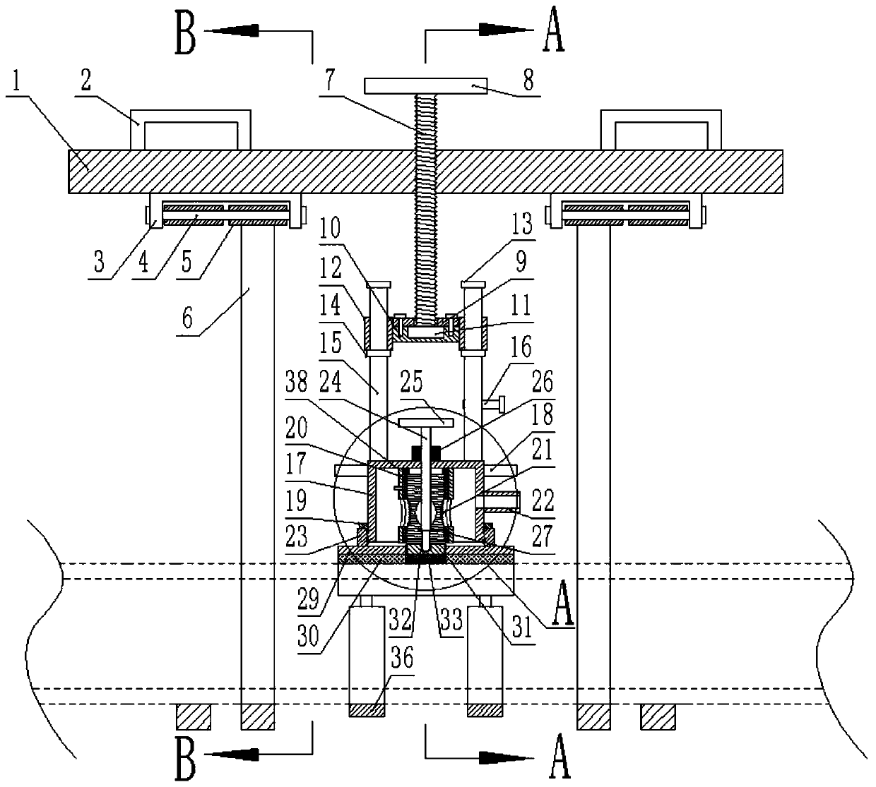
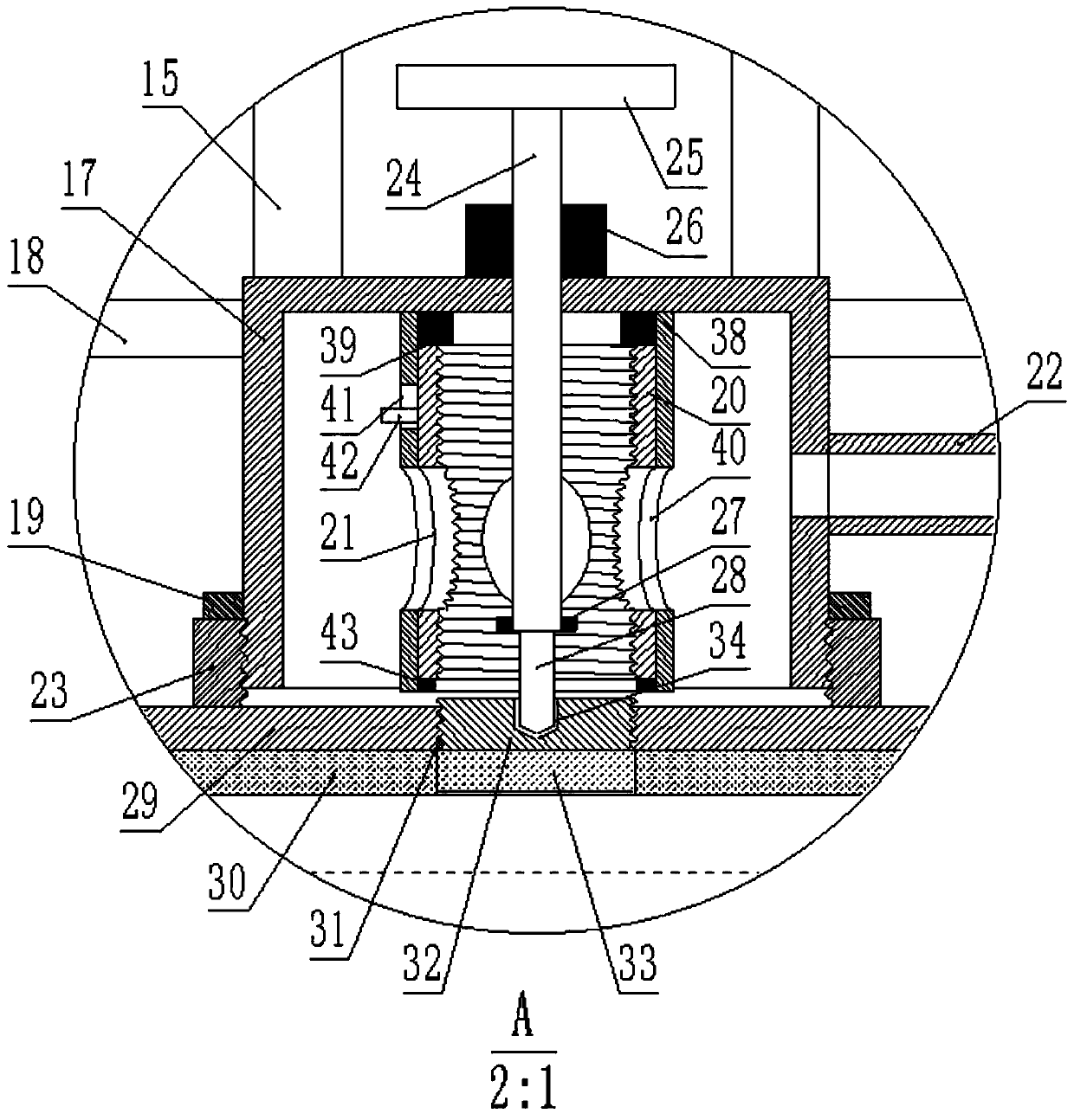
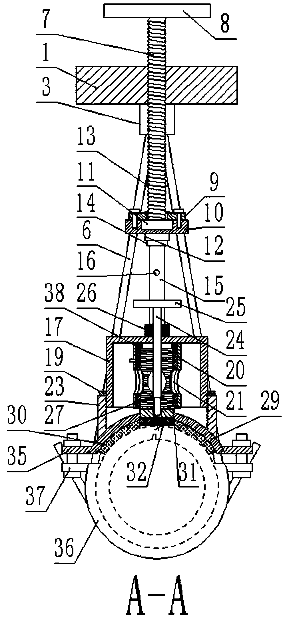
[0023] like figure 1 , figure 2 , image 3 , Figure 4 , Figure 5 , Image 6 , Figure 7 , Figure 8As shown, a water conservancy pipeline repair device that is easy to install includes a mounting plate 1, and U-shaped handles 2 are symmetrically fixed on both sides of the top surface of the mounting plate 1, respectively, and U-shaped handles 2 are symmetrically fixed on both sides of the bottom end of the mounting plate 1. U-shaped plate 3, the same pin shaft 4 runs through the two vertical plates of the U-shaped plate 3 horizontally, and the pin shaft 4 is slidingly connected with the contact point of the U-shaped plate 3, and the pin shaft 4 is sleeved with Two sleeves 5 are arranged between the two vertical plates of the U-shaped plate 3, and the sleeves 5 are rotatably connected to the pin shaft 4, and the bottom ends of the two s...


PUM


Abstract

The invention discloses a convenient-to-mount hydraulic pipeline repair device. The convenient-to-mount hydraulic pipeline repair device comprises a mounting plate, wherein the two sides of the top surface of the mounting plate are symmetrically and fixedly equipped with U-shaped handles separately. According to the device disclosed by the invention, an arc-shaped plate and a cover body are detachably arranged, so that the cover body can jack the arc-shaped plate to a pipeline damaged part after four hooks are hooked onto a pipeline, and therefore, while bearing impact force of liquid sprayedout from the pipeline damaged hole, the arc-shaped plate transmits the force onto the pipeline through the four hooks, impact pressure borne on a worker is small, and the arc-shaped plate is mounted at the pipeline damaged part conveniently; moreover, a water drainage hole is formed in the arc-shaped plate, so that liquid sprayed out from the pipeline damaged hole at high speed can be discharged from a water drainage tube, and therefore, force of impacting the arc-shaped plate by liquid is reduced, and mounting work of the arc-shaped plate is convenient; meanwhile, liquid sprayed out from thepipeline damaged hole at high speed can be guided to other parts through the water drainage tube, so that a great deal of liquid is not generated on a working site, and therefore, a worker is prevented from being in environment with a great deal of liquid for a long time.

Description

technical field [0001] The invention relates to the field of emergency repair of water conservancy pipelines, in particular to an easy-to-install water conservancy pipeline repair device. Background technique [0002] During the use of water conservancy pipelines, due to internal or external factors and other factors, leakage or damage may occur, and emergency repairs are required. The emergency repair process is completed when the water inside the pipeline is normally transported. In the prior art, pipeline repairers or welding patches are often used to repair the damaged part of the pipeline. The pipeline repairer is composed of two covers, and the two covers are buckled on the damaged part of the pipeline through the connector, so as to repair the damaged part of the pipeline. However, when the existing pipeline repair device repairs the damaged part of the pipeline, because the water flowing in the pipeline is sprayed at high speed under the transmission pressure, when t...

Claims


Application Information

Patent Timeline
Patent Type & Authority Applications(China)
IPC IPC(8): F16L55/168F16L55/17
CPCF16L55/168F16L55/17
Inventor 刘洋
Owner 宁夏银江建设工程有限公司
Learn More