
Prosthesis system with a liner and a prosthesis socket

A technology of prosthetics and bushings, applied in the field of prosthetic systems, to achieve the effect of preventing rotational movement and translational movement

Active Publication Date: 2020-06-19
OTTOBOCK SE & CO KGAA
View PDF10 Cites 0 Cited by
  • Summary
  • Abstract
  • Description
  • Claims
  • Application Information

AI Technical Summary

Problems solved by technology

[0006] The problem with the use of the bushes is that they are usually provided with a rotationally symmetrical cross-section and can thus be arranged in several different positions on the amputation stump

Method used


Image

  • Prosthesis system with a liner and a prosthesis socket
  • Prosthesis system with a liner and a prosthesis socket
  • Prosthesis system with a liner and a prosthesis socket

Examples


Embodiment Construction

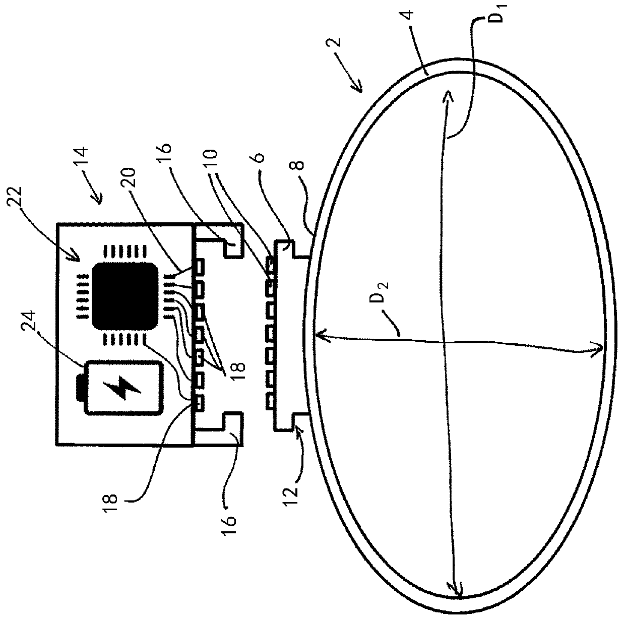
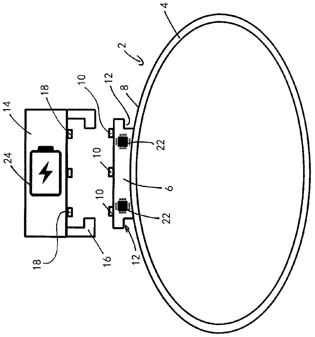
[0026] figure 1 The bushing 2 is shown in section. The shell surface 4 is shown in cross section. Instead of having a circular cross-section, the bushing has a first diameter D 1 and a second diameter D perpendicular to the first diameter 2 , the second diameter is smaller than the first diameter D 1 . The first connecting device 6 is at the second diameter D 2 It is arranged on the outer side 8 of the bushing 2 in the extension of the bushing 2 . The connecting device has an electrical contact 10 and two projections 12 via which electrical contact and mechanical locking can be achieved.

[0027] A part of the prosthesis cartridge that is not shown is the second connection device 14 , which has two hook elements 16 that interact with the projections 12 of the first connection device 6 . If the hook 16 engages with the projection 12 , the electrical contact 18 of the second connecting device bears against the electrical contact 10 of the first connecting device 8 and an ...


PUM


Abstract

The invention relates to a prosthesis system with a liner and a prosthesis socket, wherein the liner has a closed distal end, an open proximal end, a jacket surface extending from the distal end to the proximal end, and a first connecting means, and wherein the prosthesis socket has a second connecting means configured to interact with the first connecting means, wherein the first connecting meansis arranged at the jacket surface, and the first connecting means and the second connecting means are configured to produce a mechanical lock and an electrical contact between the liner and the prosthesis socket.

Description

technical field [0001] The present invention relates to a prosthesis system having a liner and a prosthesis barrel, wherein the liner has: a closed distal end; an open proximal end; a shell surface extending from the distal end to the a proximal end; and a first attachment means, wherein the prosthetic barrel has a second attachment means configured to interact with the first attachment means. Background technique [0002] Such prosthetic systems are known in a number of different designs from the prior art. In order to use the prosthesis system, the liner is first put on the amputation stump by rolling up the liner for the most part. The amputation stump is then introduced into the prosthesis sleeve via the sleeve located thereon and fastened thereto. This can be achieved by negative pressure, in that the intermediate space between the bushing and the prosthesis cartridge is sucked. In cases where such fastening is not sufficient or is not desired, various connection dev...

Claims


Application Information

Patent Timeline
Patent Type & Authority Applications(China)
IPC IPC(8): A61F2/78A61F2/80A61F2/72A61B5/0488
CPCA61F2/72A61F2/7812A61F2/80A61B5/0531A61B5/6811A61B5/389A61F2/70
Inventor M·科佩
Owner OTTOBOCK SE & CO KGAA
Learn More