

Pulp chamber approach pulp chamber opening guide plate
A technology of guide plate and pulp cavity, which is applied in medical science, dentistry, dental drilling, etc., and can solve problems such as difficulties in opening pulp holes
- Summary
- Abstract
- Description
- Claims
- Application Information
AI Technical Summary
Problems solved by technology
Method used
Image

Examples
Embodiment 1
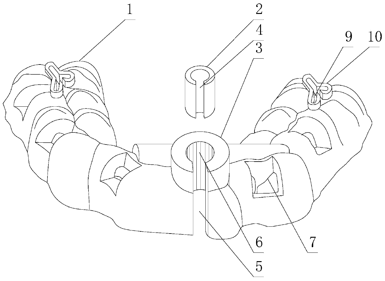
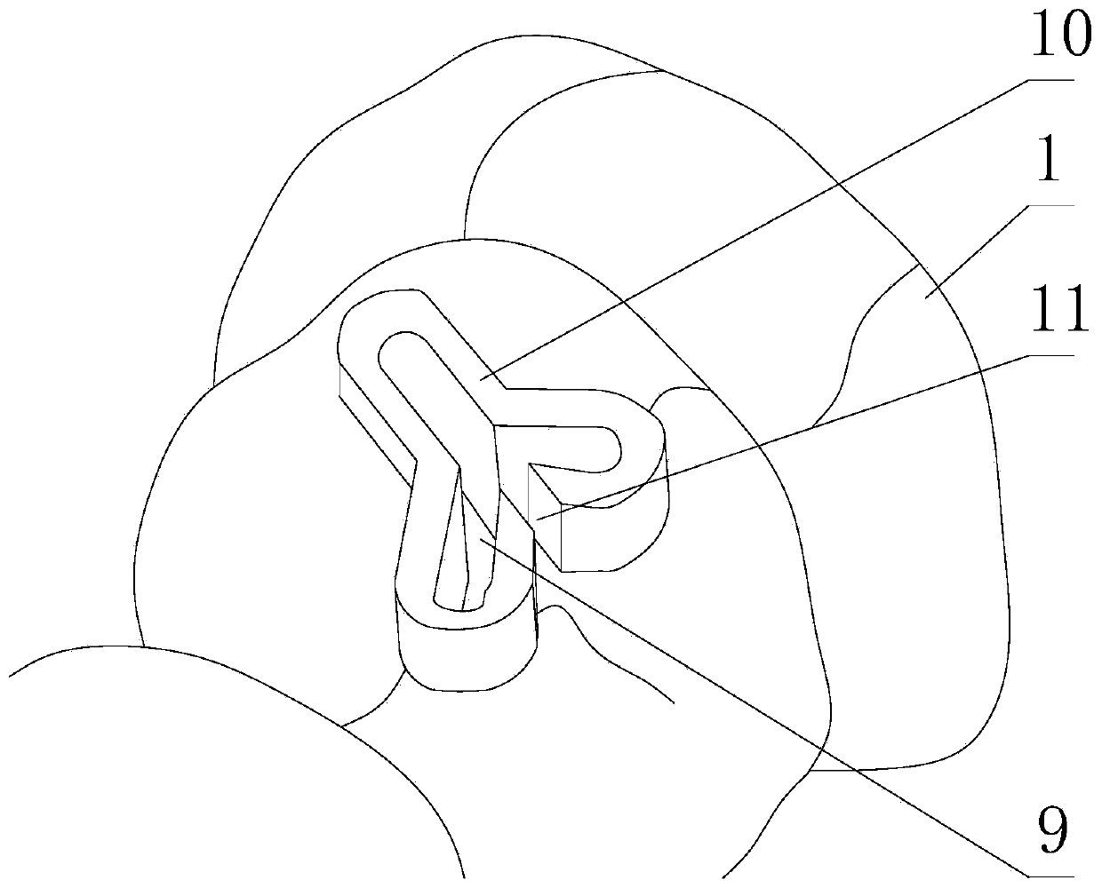
[0039] Such as Figure 1 to Figure 3 As shown, a pulp cavity approach opening guide plate includes a guide plate body 1 provided with a tooth cavity on the guide plate body 1, and a positioning hole 9 is also provided on the guide plate body 1, and the positioning hole 9 is used as the pulp chamber of the upper molar tooth and the guide hole of the root canal opening pulp hole, and also includes a stop edge 10 arranged on the guide plate body 1, the stop edge 10 is located on the side of the guide plate body 1 away from the tooth cavity, and the stop edge 10 is positioned along the positioning hole 9 edge extensions.
[0040] In the guide plate provided by this solution, the guide plate body 1 is installed in the oral cavity of the patient as a base plate as a base, and the above tooth-shaped cavity is a personalized cavity for accommodating teeth on the guide plate body 1 . In the prior art, in order to facilitate the formation of the pulp cavity and the opening boundary of ...
Embodiment 2
[0044] The present embodiment is further limited on the basis of embodiment 1, as Figure 1 to Figure 3 As shown, since the stop edge 10 is added to the existing guide plate body 1, when the bur is embedded in the positioning hole 9, compared with the case where the stop edge 10 is not provided, the patient needs to have a larger mouth opening for the same bur. The opening width, in order to avoid the above problems, is set as follows: the rim 10 is an annular structure with an opening, the opening is the third groove body 11 connecting the inner and outer sides of the annular structure, and the third groove body 11 The end is joined with the free end of the rack edge 10 . In this solution, the above third groove body 11 is used as an introduction groove for the bur to be introduced from the outside of the edge 10 to the inside of the edge 10 .
[0045] In order to realize minimally invasive pulp opening when the root canal of the affected tooth is calcified and the crown is ...
Embodiment 3
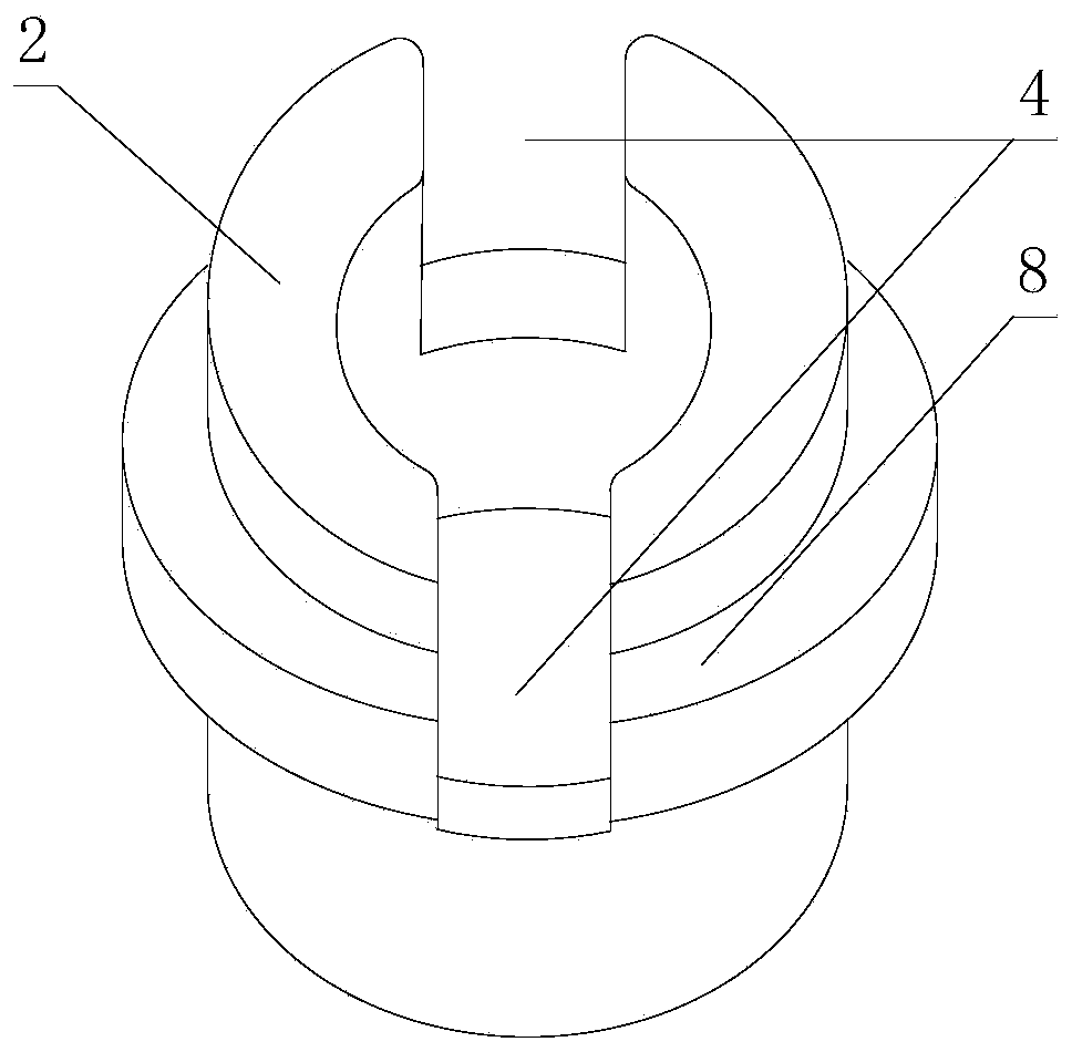
[0049] The present embodiment is further limited on the basis of embodiment 1, as Figure 1 to Figure 3 As shown, it also includes a guide cylinder 3 for guiding the incisor and canine endodontic approach needle, the center of the guide cylinder 3 is provided with a central hole 6, in the wall thickness direction of the guide cylinder 3, the guide cylinder 3 The side wall is also provided with a second groove body 5 penetrating through the side wall of the guide cylinder 3 , and one end of the second groove body 5 intersects with the side of the guide cylinder 3 away from the guide plate body 1 . In the specific design of this scheme, by being set to also include the second groove body 5, in actual use, after the installation of the guide plate body 1 is completed, taking the introduction of the bur as an example, the second groove body 5 is used as the bur by the guide cylinder 3 The side is embedded in the channel of the central hole 6. In this way, compared with the prior a...
PUM
 Abstract
Description
Claims
Application Information