Multi-airbag mechanical hand and mechanical equipment

A manipulator and multi-airbag technology, applied in the field of manipulators, can solve problems such as limiting the application range of manipulators, achieve a wide grasping range, reduce process production requirements and production costs, and have strong applicability

Pending Publication Date: 2020-06-23
JIANGXI UNIV OF SCI & TECH
View PDF0 Cites 1 Cited by
  • Summary
  • Abstract
  • Description
  • Claims
  • Application Information

AI Technical Summary

Problems solved by technology

Whether it is a rigid manipulator in the prior art or a vacuum adsorption manipulator, in the process of grabbing products for transport

Method used


Image

  • Multi-airbag mechanical hand and mechanical equipment
  • Multi-airbag mechanical hand and mechanical equipment
  • Multi-airbag mechanical hand and mechanical equipment

Examples


no. 1 example

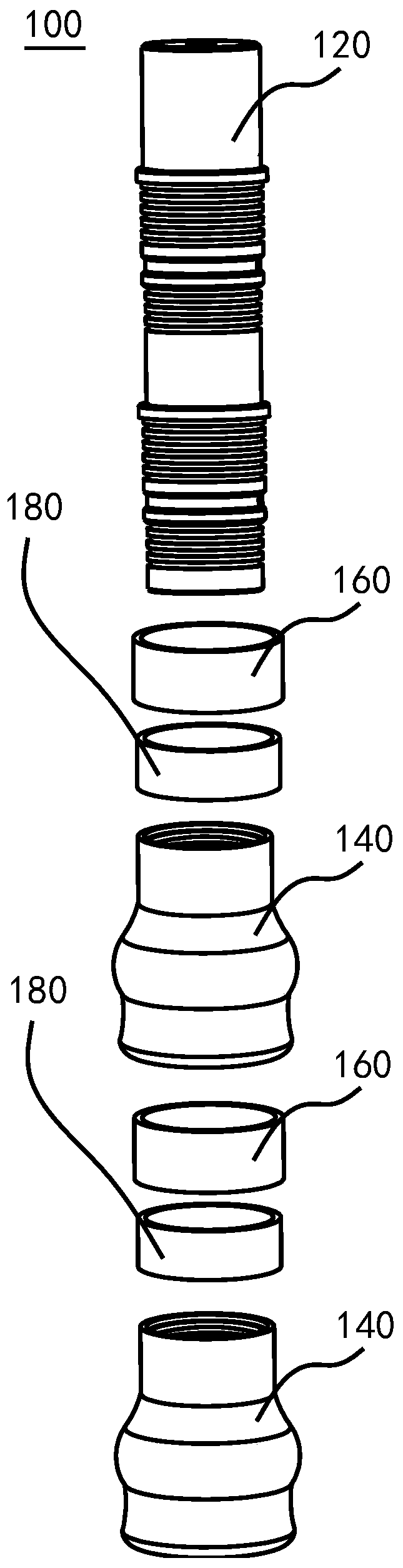
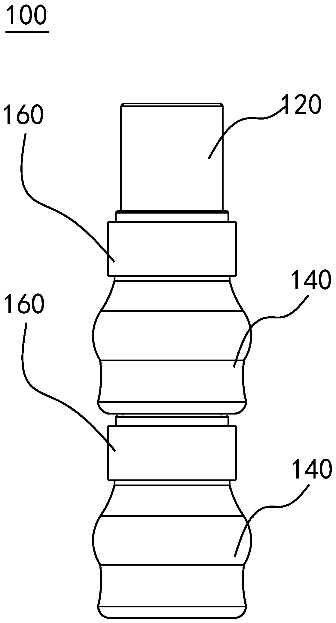
[0058] Such as Figure 1-11 As shown, the first embodiment provides a multi-airbag manipulator 100 .

[0059] see Figure 1-2 , the multi-airbag manipulator 100 includes:

[0060] The driving rod 120 is used to drive the manipulator to pick and place the target object 200;

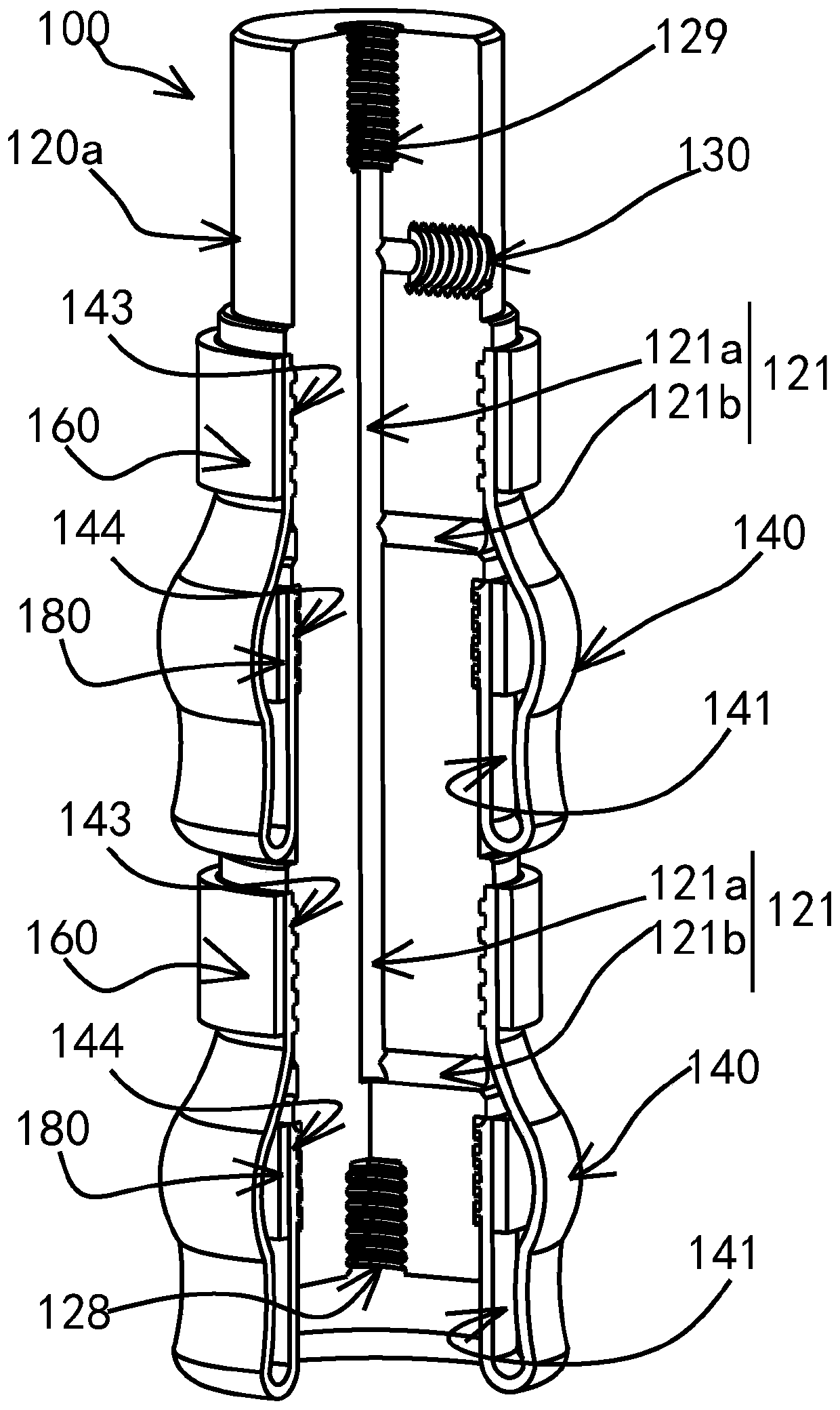
[0061] A plurality of airbags 140 are used to clamp the target object 200 during the pick-and-place work of the manipulator, and each airbag 140 in the plurality of airbags changes the shape of the airbag to adapt to the shape of the target object 200 through the airbag space 141 provided inside. To achieve clamping, the plurality of airbags 140 are respectively connected to the driving rod 120 in a manner that their respective airbag spaces 141 are wrapped on the outer wall of the driving rod 120 .

[0062] In this embodiment, the target object 200 may be an object whose inner wall needs to be grasped, such as a bottle-shaped object with a bottle mouth.

[0063] The driving rod 120 is used to drive th...

no. 2 example

[0104] continue as Figure 10-12 As shown, the second embodiment provides a mechanical device 1000, comprising

[0105] Automation equipment 300;

[0106] guide nose cone 400; and

[0107] At least one multi-airbag manipulator 100 described in the first embodiment;

[0108] Wherein, the bottom of the actuator 120a is provided with a third threaded hole 128, and the guide nose cone 400 is connected with the multi-airbag manipulator 100 through the third threaded hole 128; the automation equipment 300 and the The multi-airbag manipulators 100 are connected through the first threaded hole 129 or the second threaded hole 130 .

[0109] The object 200 in this embodiment is set as a thin-walled glass flask. Wherein, the function of the guiding nose cone is to guide the airbag manipulator 100 into the inside of the grasped object (that is, the target object 200), because the cone shape has the characteristics of convenient installation and assembly, so as to prevent the airbag 14...


PUM


Abstract

The invention discloses a multi-airbag mechanical hand. The multi-airbag mechanical hand comprises a drive rod and multiple airbags. The drive rod is used for driving the mechanical hand to take and put a target. The multiple airbags are used for clamping the target in the taking and putting work of the mechanical hand, the shape of each of the multiple airbags is changed through an airbag space arranged in the airbag to adapt to the shape of the target to achieve clamping, and the multiple airbags are connected with the drive rod in the manner that the outer wall of the drive rod is wrapped by the respective airbag spaces of the airbags correspondingly. The invention further discloses mechanical equipment with the multi-airbag mechanical hand. The shape of the multi-airbag mechanical handis easily adjusted to be matched with the target, the grabbing range is wide, and the applicability is high; the multi-airbag mechanical hand has very good flexibility, bumps and other damage to thetarget can be avoided, and the safety of the target is effectively guaranteed; and in addition, the multi-airbag mechanical hand is simple in structure and low in manufacturing cost.

Description

technical field [0001] The invention relates to the field of manipulators. More specifically, the present invention relates to a multi-airbag manipulator and mechanical equipment. Background technique [0002] With the rapid development of social economic life and technical life, the production of technical products is becoming more and more diversified, and traditional manipulators have gradually lagged behind the pace of technological development. Whether it is a rigid manipulator in the prior art or a vacuum adsorption manipulator, in the process of grabbing products for transportation, the objects to be grasped must meet certain shape requirements, which severely limits the application range of the manipulator. Contents of the invention [0003] It is an object of the present invention to solve at least the above-mentioned problems and to provide at least the advantages which will be described later. [0004] In the material production process, it is usually necessar...

Claims


Application Information

Patent Timeline
IPC IPC(8): B25J15/00
CPCB25J15/0023B25J15/0047B25J15/0052
Inventor 陈俊杰黄浩程古莹奎袁显举刘赣伟邱光琦
Owner JIANGXI UNIV OF SCI & TECH
Why Eureka
Try Eureka