
Traffic road cycle power generation system

A cycle power generation and road technology, applied in wind power generation, engines, engine components, etc., can solve problems such as high space requirements, short service life, weak power collection and conversion capabilities, and achieve the effect of multiple electric energy

Active Publication Date: 2020-06-23
WENZHOU UNIVERSITY
View PDF5 Cites 1 Cited by
  • Summary
  • Abstract
  • Description
  • Claims
  • Application Information

AI Technical Summary

Problems solved by technology

However, the power collection and conversion capabilities of this piezoelectric power harvesting system are weak, and the service life is shorter than that of the traditional power generation system that cuts magnetic lines of force to generate power.
[0003] However, the traditional coil cutting magnetic field line power generation system needs to apply power to the coil to convert mechanical energy into electrical energy, which has high space requirements, and the traditional construction system cannot make it suitable for road traffic logistics power generation.

Method used


Image

  • Traffic road cycle power generation system
  • Traffic road cycle power generation system
  • Traffic road cycle power generation system

Examples


Embodiment Construction

[0027] The present invention will be described in further detail below in conjunction with the accompanying drawings and embodiments. Wherein the same components are denoted by the same reference numerals. It should be noted that the words "front", "rear", "left", "right", "upper" and "lower" used in the following description refer to the directions in the drawings, and the words "bottom" and "top "Face", "inner" and "outer" refer to directions toward or away from, respectively, the geometric center of a particular component.

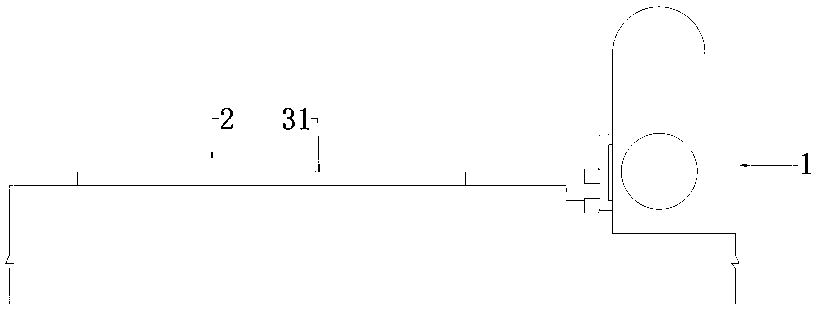
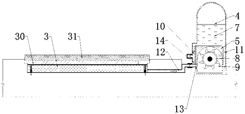
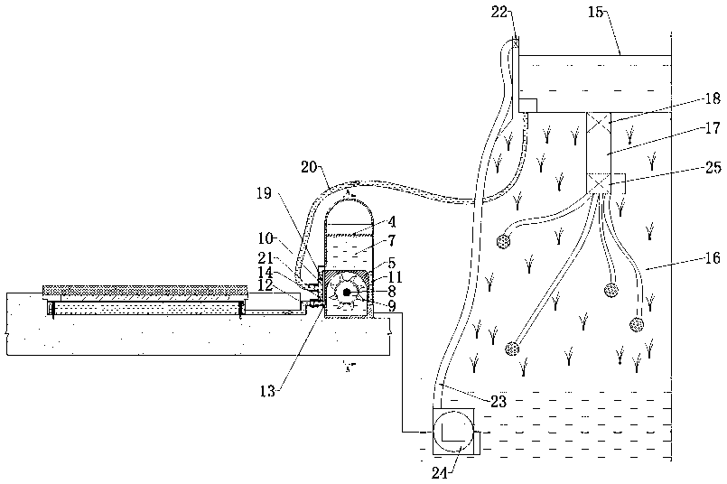
[0028] refer to Figure 1-8 As shown, a traffic road cycle power generation system provided by the present invention includes an energy conversion device 1 and a road pressure bearing mechanism 2. The pressure bearing mechanism 2 includes a liquid chamber 3 under the road. The chamber 3 transmits pressure. In this embodiment, the liquid chamber 3 is provided with a piston 30, the liquid chamber 3 is an elastic chamber, and the piston 30 is rigidly con...


PUM


Abstract

The invention discloses a traffic road cycle power generation system. The traffic road cycle power generation system comprises an energy conversion device and a road pressure bearing mechanism, wherein the pressure bearing mechanism comprises a liquid accommodating cavity below a road, the energy conversion device comprises a shell, a sealing cover and an isolation cover I, the upper portion of the shell is provided with a plurality of batteries connected by wires, the lower portion of the shell is provided with a generator I connected with the storage batteries through a wire, the sealing cover is removably connected with the shell, a space between the sealing cover and the shell constitutes a liquid circulation cavity, a rotating shaft of the generator I extends into the liquid circulation cavity, the liquid circulation cavity is internally provided with the isolation cover I and an impeller I connected with the rotating shaft, the liquid accommodating cavity is connected with a leftwater circulation channel through a guide pipe, a first one-way valve communicating with the inner side of the isolation cover I is arranged at the joint between the isolation cover I and the guide pipe, and a second one-way valve communicating with the guide pipe in a unidirectional direction is arranged at the joint between the left water circulation channel and the guide pipe. The system is better in durability, higher in energy conversion, and capable of collecting power from more sources.

Description

technical field [0001] The invention relates to a traffic road circulation power generation system. Background technique [0002] Piezoelectric power generation systems for road logistics have been widely used. With the popularization of the application of piezoelectric materials, there have been occasions at home and abroad where piezoelectric materials are used for power generation. Piezoelectric materials are applied to speed bumps. Transform the pressure of the car on the speed bump into the vibration of the piezoelectric vibrator. However, the piezoelectric power harvesting system has weak power collection and transformation capabilities, and its service life is shorter than that of the traditional power generation system in which coils cut magnetic lines of force to generate power. [0003] However, the traditional coil-cutting magnetic field line power generation system needs to apply power to the coil to convert mechanical energy into electrical energy, which has hi...

Claims


Application Information

Patent Timeline
Patent Type & Authority Applications(China)
IPC IPC(8): F03G7/00F03B13/00F03D9/25F04D13/04A01G25/00
CPCF03G7/00F03B13/00F03D9/008F03D9/25F04D13/04A01G25/00F05B2220/706Y02E10/72
Inventor 余闯吴则祥沈颜李博顾雯浩吕金晶
Owner WENZHOU UNIVERSITY
Learn More