Equipment control method and device, control node, network equipment and data center

A technology for device control and control nodes, which is applied in the network field and can solve problems such as difficult access control

Inactive Publication Date: 2020-06-23
ZTE CORP
View PDF4 Cites 1 Cited by
  • Summary
  • Abstract
  • Description
  • Claims
  • Application Information

AI Technical Summary

Problems solved by technology

[0004] The device control method, device, control node, network device, and data center provided by the embodiments of the present invention mainly solve the technical problem that when accessi

Method used


Image

  • Equipment control method and device, control node, network equipment and data center
  • Equipment control method and device, control node, network equipment and data center
  • Equipment control method and device, control node, network equipment and data center

Examples


Embodiment 1

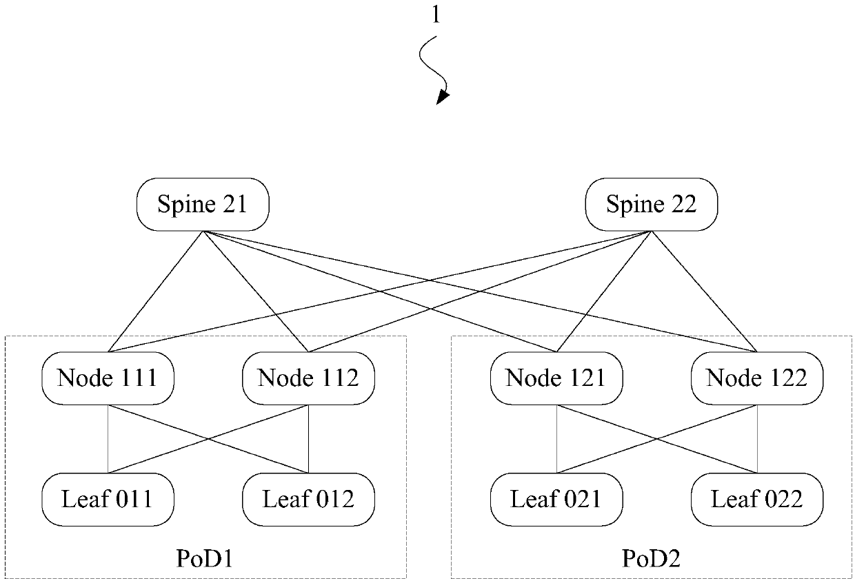
[0046] First, see figure 1 A schematic diagram of the data center shown in : the devices in data center 1 are divided into Layer 2 devices, Layer 1 devices, and Layer 0 devices from top to bottom. In some examples, Layer 2 is also called "core layer "(core), layer 1 is called the "aggregate layer", and layer 0 is called the "edge layer". exist figure 1 Among them, Layer 2 devices include Spine21 and Spine 22; Layer 1 devices include Node 111, Node 112, Node 121, and Node122; Layer 0 devices include Leaf011, Leaf 012, Leaf 021, and Leaf 022.

[0047] In the data center, there is the concept of "PoD" (Point of Delivery, delivery point), and PoD is also called "area". Among them, Node 111, Node 112, Leaf 011, and Leaf 012 belong to PoD1, and Node 121, Node 122, Leaf021, and Leaf 022 belong to PoD2.

[0048] When accessing the device in the data center in related technologies, it is necessary to log in to the device. For example, if the network administrator needs to configure ...

Embodiment 2

[0086] The first embodiment introduces a device control method that can be applied to a control node, and this embodiment will introduce a device control method that is applied to a device on a non-control node in a data center. It can be understood that devices that are not control nodes in the data center are devices that belong to PoD. In this embodiment, in order to distinguish these devices from control nodes, we call them PoD network devices:

[0087] see below Figure 4 A flow chart of a device control method applied to a PoD network device is shown:

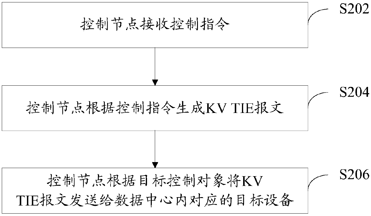
[0088] S402: The PoD network device receives the KV TIE message from the control node.

[0089] The PoD network device will receive the KV TIE message sent by the control node. It is understandable that the receiving "KV TIE message from the control node" here does not mean that the PoD network device receives it directly from the KV TIE message. It is only to illustrate that the KV TIE message is sent from the control ...

Embodiment 3

[0124] In order to make those skilled in the art more aware of the advantages and details of the device control method provided in the foregoing embodiments, this embodiment will continue to introduce the process of the device control method controlling the node side and the PoD network device side with specific examples:

[0125] The following takes the KV TIE message as an example of a KV S-TIE message for illustration: In this embodiment, a device in the data center is scheduled to extend the RIFT protocol key TIE so that the KV S-TIE message supports control. The key-value TIE structure defined by RIFT is {KeyID, Value}. In this example, KeyID is used as the key, and the KV S-TIE packet is defined to include the following fields:

[0126] WORD16TYPE field, wherein, when TYPE=1, it means that the KV S-TIE message is the control parameter type;

[0127] The WORD16ControlID field is used to represent the type of ControlData, that is, to indicate the control item;

[0128...


PUM


Abstract

The embodiment of the invention provides an equipment control method and device, a control node, network equipment and a data center. Equipment in a data center network is controlled and managed basedon an RIFT technology. When access control needs to be carried out on a certain device in a data center network, a network manager only needs to issue a control instruction on the control node equipment; and specifying the target control object, the to-be-controlled item and the value of the to-be-controlled item. The control node equipment generates a KV TIE message according to the received control instruction; transmitting the information to corresponding target equipment; the target equipment completes control corresponding to the control instruction; network management personnel do not need to log in the target device, netconf connection between the management server and the target device does not need to be established specially, the access control process of the data center networkdevice is simplified, the time cost of access control is reduced, the access control efficiency is improved, and the management mechanism of the data center network is optimized.

Description

technical field [0001] The present invention relates to the network field, in particular to a device control method, device, control node, network device and data center. Background technique [0002] The data center network generally uses the fat tree (Fat Tree) technology, and the devices therein are usually divided into three layers, which are layer 2, layer 1, and layer 0. Layer 2 is the top layer in the data center network, and layer 0 is the bottom layer of the data center network. Therefore, there are usually not many devices on layer 2, but the number of devices on layer 1 and layer 0 is relatively large, especially the number of devices on layer 0 is tens of thousands. In related technologies, when controlling devices in the data center Or access, mainly through netconf (IETF established the Netconf working group in May 2003, which was mainly established to propose a new XML-based network configuration (NETCONF) protocol) or MIB (Management Information Base, Both ...

Claims


Application Information

Patent Timeline
IPC IPC(8): H04L29/06H04L29/08
CPCH04L67/146H04L63/10H04L69/22H04L67/60H04L41/08H04L41/28H04L12/44
Inventor 徐本崇张征王会来
Owner ZTE CORP
Why Eureka
Try Eureka