Bolt locking device

A locking device and bolt technology, applied in the field of machinery, can solve problems such as inconsiderate bolt alignment and reduced work efficiency

Inactive Publication Date: 2020-06-26
DONGGUAN XIANGFEI INTELLIGENT EQUIP TECH CO LTD
0 Cites 2 Cited by

AI-Extracted Technical Summary

Problems solved by technology

[0003] The existing bolt locking device does not consider the straightening of the bolts very carefully, which leads to the need to replace the bolts when clamping the bolts. After the ...

Method used

The inner top right side of described frame 1 is equipped with hanging plate 12, and the bottom surface of hanging plate 12 is provided with slide rail 13, and locking device 14 is installed above described slide rail 13, and described frame 1 A chute 15 is installed on the right side of the inner bottom, and a clamping device 16 is arranged above the chute 15. The size of the slide rail 13 matches the locking device 14, and the locking device 14 and the sliding rail 13 form a sliding structure, throu...

Abstract

The invention discloses a bolt locking device. The bolt locking device comprises a rack, a clamping device, a locking device and a holding device, wherein the upper left portion of the interior of therack is provided with a vibration screening disc, three rotary rods are uniformly matched on the outer wall of a bearing, a rotary shaft is arranged on the inner wall of an inner ring of the vibration screening disc, the clamping device is cooperatively arranged below a conveying platform, and a baffle is installed above another transmission roller; limiting grooves are formed above a clapboard,and the locking device is cooperatively arranged above the clamping device. According to the bolt locking device, a motor drives the bearing to rotate to convey first bolts in the vibration screeningdisc onto the conveying platform, then the bottoms of bolt rods exactly fall into the grooves to straighten the bolts, and the first bolts are jacked up through telescopic rod and are clamped by the locking device; through the arrangement of down lights, storage batteries and guide wires, bolt holes are irradiated, and the irradiating light makes it convenient to quickly find the bolt holes through the locking device, so that the first bolts are locked.

Application Domain

Metal working apparatus

Technology Topic

Clip deviceClapboard +6

Image

  • Bolt locking device
  • Bolt locking device
  • Bolt locking device

Examples

  • Experimental program(1)

Example Embodiment

[0027] The technical solutions in the embodiments of the present invention will be clearly and completely described below in conjunction with the accompanying drawings in the embodiments of the present invention. Obviously, the described embodiments are only a part of the embodiments of the present invention, rather than all the embodiments.
[0028] In the description of the present invention, unless otherwise specified, "plurality" means two or more; the terms "upper", "lower", "left", "right", "inner", "outer" , "Front", "Back", "Head", "Tail", etc. indicate the orientation or positional relationship based on the orientation or positional relationship shown in the drawings, and are only for the convenience of describing the present invention and simplifying the description, not Indicates or implies that the device or element referred to must have a specific orientation, be constructed and operated in a specific orientation, and therefore cannot be understood as a limitation of the present invention. In addition, the terms "first", "second", "third", etc. It is used for descriptive purposes only, and cannot be understood as indicating or implying relative importance.
[0029] In the description of the present invention, it should be noted that the terms "connected" and "connected" should be understood in a broad sense unless otherwise clearly specified and limited. For example, they may be fixed connection, detachable connection, or integral Ground connection; it can be a mechanical connection or an electrical connection; it can be a direct connection or an indirect connection through an intermediary. For those of ordinary skill in the art, the specific meaning of the above terms in the present invention can be understood under specific conditions .
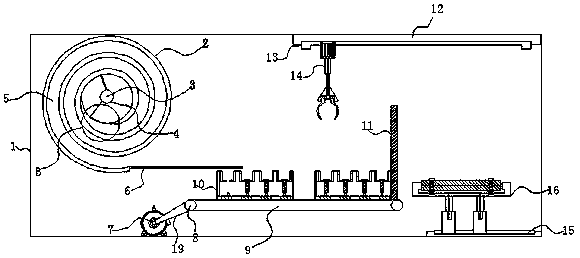
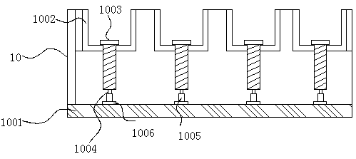
[0030] See Figure 1 to Figure 6 , The present invention provides a technical solution: a bolt locking device, comprising a frame 1, a clamping device 10, a locking device 14 and a clamping device 16, and a vibration screening disc is provided on the upper left of the frame 1 2. A bearing 3 is installed in the center of the vibrating screen disc 2. The outer wall of the bearing 3 is evenly matched with three rotating rods 4, and the inner wall of the inner ring of the vibrating screen disc 2 is provided with a rotating shaft 18, and the rotating shaft 18 and the rotating rod 4 The ends are connected, the outer wall of the rotating shaft 18 is fixed with a fence 17, the inside of the vibrating screen plate 2 is provided with a conveying channel 5, and the exit of the conveying channel 5 is connected with a conveying platform 6, and the conveying platform 6 A clamping device 10 is fitted below, and a conveyor belt 9 is installed under the clamping device 10. The two ends of the conveyor belt 9 are sleeved with transmission rollers 8, and one end of the conveyor belt 9 is connected with a transmission belt 19, and the transmission belt A stepping motor 7 is connected to the end of 19, a baffle 11 is installed above the other end of the conveyor belt 9, and the clamping device 10 includes a partition 1001, a limiting groove 1002, a first bolt 1003, and a telescopic rod 1004 , The rod sleeve 1005 and the base 1006, and the inner bottom of the clamping device 10 is provided with a partition 1001, a limiting groove 1002 is installed above the partition 1001, and a first bolt 1003 is provided inside the limiting groove 1002, so The upper surface of the partition 1001 is provided with a base 1006, and a rod sleeve 1005 is installed on the upper surface of the base 1006, the top of the rod sleeve 1005 is connected with a telescopic rod 1004, and the telescopic rod 1004 is connected with the bottom of the first bolt 1003 A locking device 14 is fitted above the clamping device 10, and a clamping device 16 is fitted on the right side of the clamping device 10.
[0031] The clamping device 10 is provided with a limiting slot 1002 inside, and there are four limiting slots 1002 equidistantly arranged along the horizontal direction of the clamping device 10, and the clamping device 10 and the conveyor belt 9 are connected by a buckle. , And the clamping device 10 is arranged equidistantly along the direction of the conveyor belt 9, and the motor drives the rotation of the bearing 3, so that the first bolt 1003 in the vibrating screening disc 2 is sent to the conveying platform 6, and then conveyed by the conveying platform 6, The first bolt 1003 just falls into the limiting groove 1002 inside the clamping device 10. Since the length of the limiting groove 1002 matches the length of the first bolt 1003, the bottom of the rod of the first bolt 1003 just falls off When the first bolt 1003 is installed in a limit slot 1002, the drive belt 19 is driven to rotate by the stepping motor 7, so that the drive roller 8 drives the clamping device 10 on the conveyor belt 9 to move in the conveying direction. Perform the next first bolt 1003 alignment. When the clamping device 10 is full, the conveyor belt 9 will be transported until the baffle 11 stops, and then through the internal telescopic structure of the clamping device 10, the first bolt 1003 lifts up to allow the locking device 14 to clamp.
[0032] A hanging plate 12 is installed on the right side of the inner top of the rack 1, and a slide rail 13 is provided on the bottom surface of the hanging plate 12, a locking device 14 is installed above the slide rail 13, and the inner bottom right of the rack 1 A sliding groove 15 is installed on the side, and a clamping device 16 is arranged above the sliding groove 15. The sliding rail 13 and the locking device 14 are matched in size, and the locking device 14 and the sliding rail 13 form a sliding structure. The sliding structure of the slide rail 13 and the locking device 14 can move the locking device 14 on the slide rail 13 under the action of the swing cylinder 1401. The electric push rod 1404 inside the locking device 14 pushes the clip 1409 to expand and contract. To reach the top of the clamping device 10, at the same time, the first bolt 1003 is lifted up by the telescopic structure at the bottom of the clamping device 10, so that the first bolt 1003 can be clamped by the clamp 1409 conveniently.
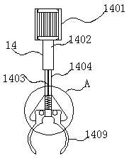
[0033] The locking device 14 includes a swing cylinder 1401, an electric rod sleeve 1402, a steel wire 1403, an electric push rod 1404, a spring sleeve 1405, a spring 1406, a triangle mounting seat 1407, a second bolt 1408 and a clip 1409, and the swing cylinder 1401 The output end is provided with an electric rod sleeve 1402, the bottom end of the electric rod sleeve 1402 is connected to one end of the electric push rod 1404, and the other end of the electric push rod 1404 is provided with a spring sleeve 1405 inside of the spring sleeve 1405 A spring 1406 is installed, the electric push rod 1404 is provided with a triangular mounting seat 1407 on the outside, and a clip 1409 is installed at the bottom of the triangular mounting seat 1407, one end of the spring 1406 is welded with a steel wire 1403, and the steel wire 1403 penetrates the electric push rod 1404 The other end of the spring 1406 is connected to the clip 1409, the spring 1406 and the steel wire 1403 are welded, and the clip 1409 forms an elastic structure through the spring 1406. The triangular mounting seat 1407 It is connected with the clip 1409 by the second bolt 1408, and the triangular mounting seat 1407 and the clip 1409 constitute a detachable structure. Through the welding between the steel wire 1403 and the spring 1406, the spring 1406 can be driven when the electric push rod 1404 is extended and retracted. Shrink, so that the clamp 1409 can be loosened and clamped. The second bolt 1408 is connected between the triangular mounting seat 1407 and the clamp 1409. When the clamp 1409 needs to be replaced, the second bolt 1408 can be easily unloaded and replaced with a new one. After the clip 1409 is clamped, the second bolt 1408 is used for locking.
[0034] The clamping device 16 includes a guide sleeve 1601, a guide post 1602, a clamping block 1603, a downlight 1604, a wire 1605, a battery 1606, a lower clamp 1607, an upper clamp 1608 and a nut 1609, and a guide sleeve 1601 is connected above the guide sleeve 1601. The bottom of the guide column 1602 is equipped with a battery 1606, the top of the guide column 1602 is connected with a clamping block 1603, and the opening of the clamping block 1603 is provided with a lower clamp 1607, above the lower clamp 1607 An upper clamp 1608 is installed, and a first bolt 1003 penetrates between the upper clamp 1608 and the lower clamp 1607. The inner bottom surface of the clamping block 1603 is provided with a downlight 1604, and the downlight 1604 and the battery 1606 are electrically connected through a wire 1605 Connection, through the downlight 1604 on the inner bottom of the clamping block 1603, the bottom of the guide post 1602 to connect the battery 1606 and the electrical connection wire 1605 to irradiate the bolt hole, and the irradiated light can facilitate the locking device 14 to quickly find the bolt Hole to lock the first bolt 1003.
[0035] In summary, the bolt locking device first puts the first bolt 1003 into the vibrating screening disc 2 during use, and the motor drives the bearing 3 to rotate, thereby driving the rotating rod 4 to rotate, so that the first bolt 1003 is pushed , The fence 17 is opened by turning on the button of the shaft 18, and the first bolt 1003 slides in the conveying lane 5, so that the first bolt 1003 is sent to the conveying platform 6, and the conveying platform 6 makes the first bolt 1003 just falls into the limit groove 1002 inside the clamping device 10. Since the length of the limit groove 1002 matches the length of the first bolt 1003, the bottom of the rod of the first bolt 1003 just falls into the groove. Straightening, when a limit slot 1002 is installed in the first bolt 1003, the stepping motor 7 drives the transmission belt 19 to rotate, so that the transmission roller 8 drives the clamping device 10 on the conveyor belt 9 to move in the conveying direction to proceed to the next first A bolt 1003 is set up. When the clamping device 10 is full, the conveyor belt 9 will be conveyed to the position of the baffle 11 to stop. Through the internal telescopic structure of the clamping device 10, the first bolt 1003 will be lifted up to allow The locking device 14 is clamped. At this time, the locking device 14 can move the locking device 14 on the slide rail 13 under the action of the swing cylinder 1401 through the sliding structure formed with the slide rail 13, and the locking device 14 The internal electric push rod 1404 pushes the clamp 1409 to expand and contract, reaching the top of the clamping device 10, and clamps the first bolt 1003. After clamping, the clamp 1409 clamps the first bolt 1003 by the action of the swing cylinder 1401. , Move to the top of the clamping device 16, through the downlight 1604 on the inner bottom of the clamping block 1603, the bottom of the guide post 1602 to connect the battery 1606 and the electrically connected wire 1605 to irradiate the bolt hole, and the irradiated light makes the lock The tightening device 14 quickly finds the position of the bolt hole. Through the clamping block 1603 at the top of the guide column 1602, the upper clamp 1608 and the lower clamp 1607 are fixed and clamped, so that the first bolt 1003 is inserted into the locking device 14, and then swing The rotation of the air cylinder 1401 causes the first bolt 1003 to rotate, so that the upper clamp 1608 and the lower clamp 1607 are tightly locked together.
[0036] The above are only preferred specific embodiments of the present invention, but the protection scope of the present invention is not limited to this. Anyone familiar with the technical field within the technical scope disclosed by the present invention, according to the technical solution of the present invention The equivalent replacement or change of the inventive concept thereof shall be covered by the protection scope of the present invention.

PUM

no PUM

Description & Claims & Application Information

We can also present the details of the Description, Claims and Application information to help users get a comprehensive understanding of the technical details of the patent, such as background art, summary of invention, brief description of drawings, description of embodiments, and other original content. On the other hand, users can also determine the specific scope of protection of the technology through the list of claims; as well as understand the changes in the life cycle of the technology with the presentation of the patent timeline. Login to view more.
Why Eureka
Try Eureka