
Brittle silver ore dividing machine

A technology of shrinking machine and ore, which is applied in the field of ore machinery, can solve the problems such as the breaking of cutting blocks, and achieve the effect of expanding the display area.

Active Publication Date: 2020-06-26
新沂市久元矿业有限公司
View PDF6 Cites 0 Cited by
  • Summary
  • Abstract
  • Description
  • Claims
  • Application Information

AI Technical Summary

Problems solved by technology

[0006] In order to solve the above-mentioned technology, because the material of the brittle silver ore is relatively fragile, it is fixed in the middle sleeve, and when the outer sleeve is slidingly cut, when the protruding part and the concentrated part of the middle section are tightly bonded, it is easier to The problem that the cutting block breaks after cutting

Method used


Image

  • Brittle silver ore dividing machine
  • Brittle silver ore dividing machine
  • Brittle silver ore dividing machine

Examples


Embodiment 1

[0031] as attached figure 1 to attach Figure 4 Shown:

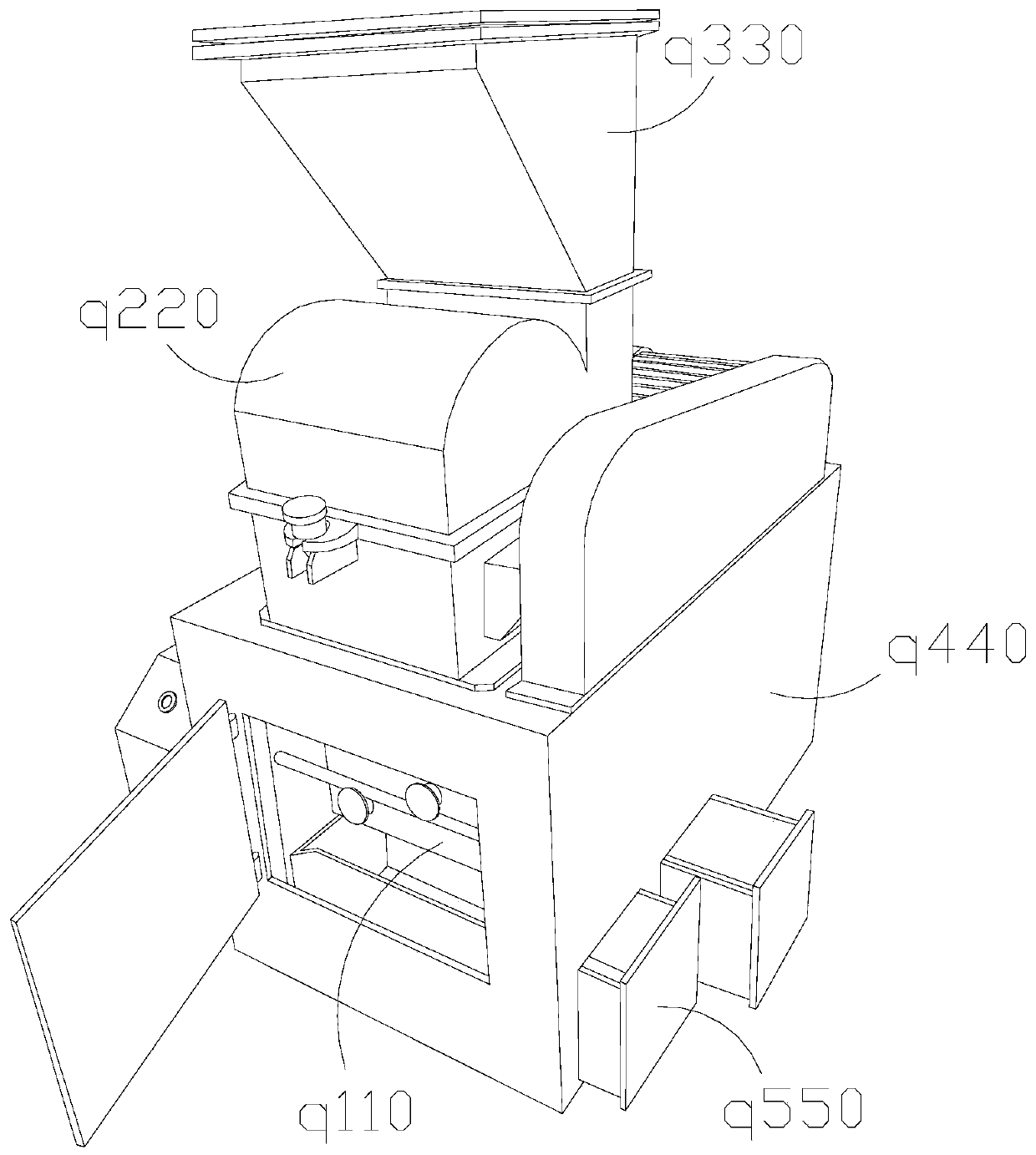
[0032] The present invention provides a brittle silver ore shrinking machine, the structure of which includes an internal control box q110, a shrinking pipe q220, a material barrel q330, a main body q440, and a sorting drawer q550.

[0033] The internal control box q110 is welded to the inner wall of the main housing body q440, and the upper surface of the main housing body q440 is penetrated with a shrinkage pipe q220, which is connected with the internal control box q110. The q330 communicate with each other, and the sorting drawer q550 is located inside the main body q440 and is movably connected.

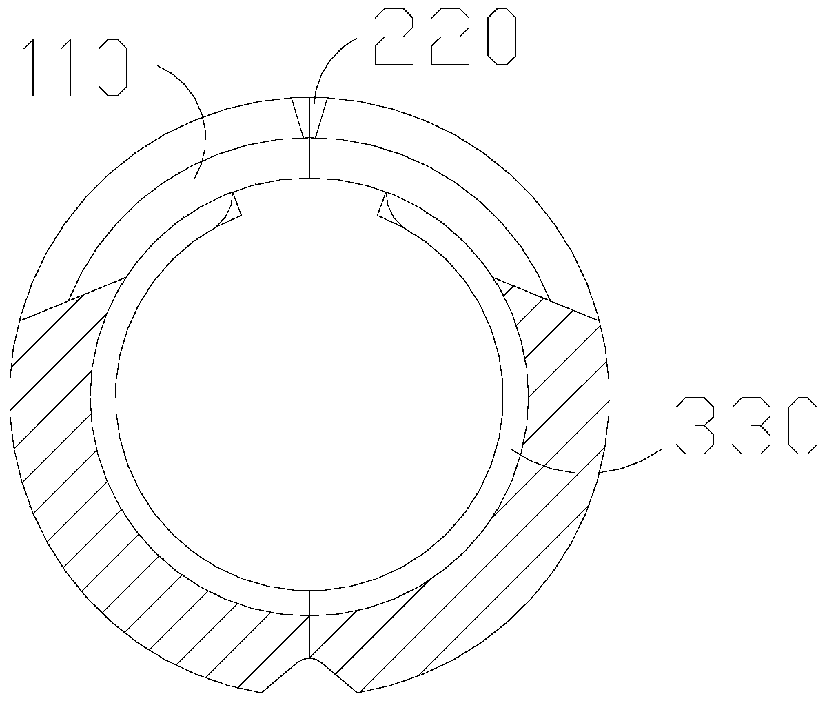
[0034] Wherein, the shrinking and dividing pipe q220 includes a shrinking and dividing ring 110, an opening 220, and an inner solid layer 330. The opening 220 and the shrinking and dividing ring 110 are an integrated structure, and the inner wall of the shrinking and dividing ring 110 is against the inner solid layer 330...

Embodiment 2

[0041] as attached Figure 5 to attach Figure 8 Shown:

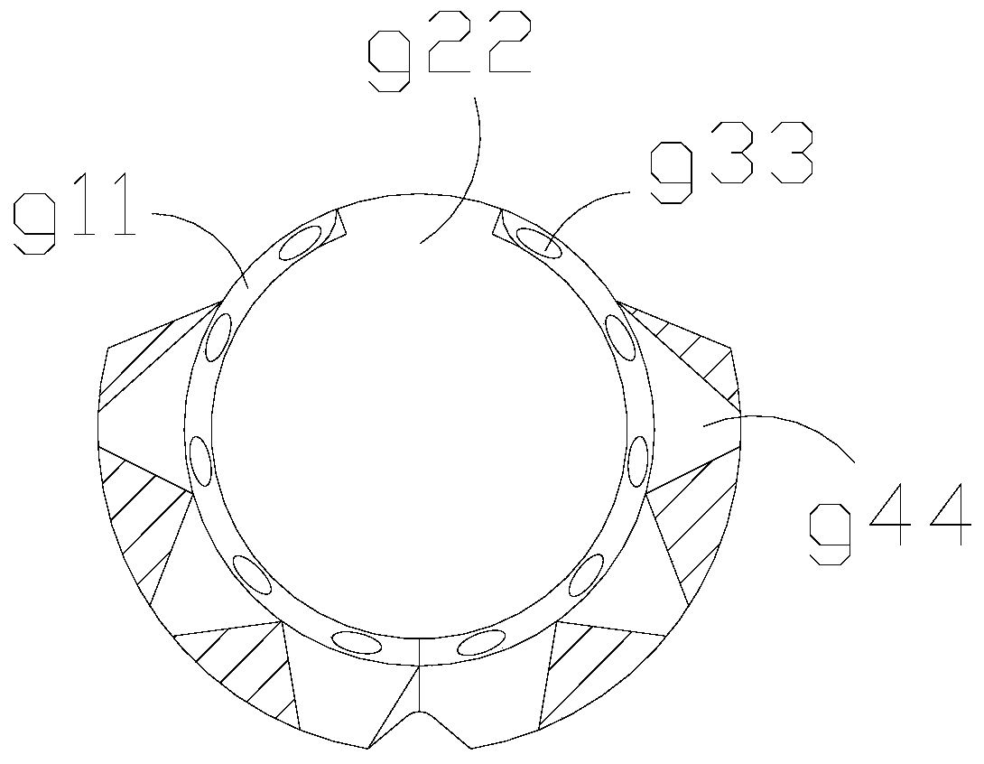
[0042] Wherein, the opening arc 50 includes an inclination strip r01, a direction bar r02, a swing head r03, and a pullback arc r04. One end of r02 is connected with the anti-tear arc r04, the swing head r03 is wrapped on the outer surface of the support bar r02, there are two swing heads r03, the inclination bar r01 is in a fan-shaped structure, and the support bar The strip r02 drives the whole body to bear the force of the rear end. The inclined strip r01 has no effect on the outer layer when it is static. When it is bent by force, it drives the outer layer to pull down. When head r03 is active, wrap in one direction.

[0043] Wherein, the supporting bar r02 includes an extension angle e1, an expanding edge e2, and a middle ring e3, and the extending angle e1 is installed on the outer surface of the expanding edge e2, and the end of the expanding edge e2 far away from the extending angle e1 is connected to the mid...


PUM


Abstract

The invention discloses a brittle silver ore dividing machine. The machine structurally comprises an inner control box, a dividing pipe, a containing barrel and a main containing body, wherein the inner control box is welded to the inner wall of the main containing body, and the dividing pipe penetrates through the upper surface of the main containing body and is connected with the inner control box. According to the machine, a dividing ring and an inner fixing layer are unfolded into two halves through an unfolding opening; the inner fixing layer abuts against the surface of ore through the combined force of the inner fixing layer; side arc rubber is arranged between uniform abutting blocks and a following attaching arc; when the fragile silver ore is placed in a treatment pipe, concave-convex shape fixing is carried out on the fragile silver ore according to the surface of the ore; the dividing ring move along the surface size of the inner fixing layer in an attached mode, and a dividing head and an opening arc move along with the abutting force; a middle supporting ball at the upper end can be connected with the force supported by and attached to the outer side, and the acting area of the connecting force is enlarged; an expanding supporting edge assists in pulling, and a middle ring continues to drag a reverse pulling arc at the outer side of a direction supporting strip; and after the fragile silver ore is divided, the two parts after division of the fragile silver ore can be pushed and wrapped to different degrees.

Description

technical field [0001] The invention belongs to the field of ore machinery, and more specifically relates to a brittle silver ore shrinking machine. Background technique [0002] The ore shrinking machine is to cut and sample a part of the small ore with double casings. There are many kinds of ores processed by the shrinking machine. The shape of the brittle silver ore itself is relatively concentrated, and the shape will be slightly smaller. The parts are transported and placed separately. [0003] Based on the inventor's discovery above, existing ore shrinking and dividing machines mainly have the following deficiencies, such as: [0004] Since the material of brittle silver ore is relatively fragile, it is fixed in the middle casing, and when the outer casing is slidingly cut, when the protruding part and the concentrated part of the middle part are tightly bonded, it is easier to follow the cutting after cutting The block breaks apart. [0005] Therefore need to propo...

Claims


Application Information

Patent Timeline
IPC IPC(8): B28D1/22B28D7/04B28D7/00G01N1/04G01N1/28
CPCB28D1/22B28D7/00B28D7/04G01N1/04G01N1/286G01N2001/2873
Inventor 黄瑞良
Owner 新沂市久元矿业有限公司
Learn More