
Tubular heat exchanger

A technology of tubular heat exchanger and heat exchange tube, applied in the direction of heat exchanger shell, indirect heat exchanger, heat exchanger type, etc. quality and other issues, to avoid trouble, reduce the possibility of scale generation, and avoid cleaning heat exchange components

Inactive Publication Date: 2020-06-26
宁夏绿源实业有限公司
View PDF0 Cites 4 Cited by
  • Summary
  • Abstract
  • Description
  • Claims
  • Application Information

AI Technical Summary

Problems solved by technology

[0005] The purpose of the present invention is to provide a tubular heat exchanger to solve the problems in the prior art that the tubular heat exchanger is easy to foul and difficult to clean, which affects the heat exchange quality and the life of the heat exchanger

Method used


Image

  • Tubular heat exchanger
  • Tubular heat exchanger
  • Tubular heat exchanger

Examples


Embodiment 1

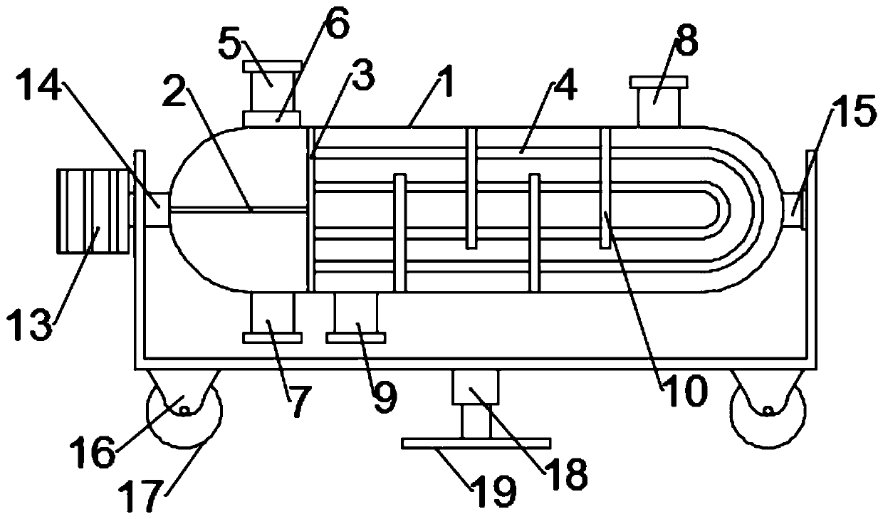
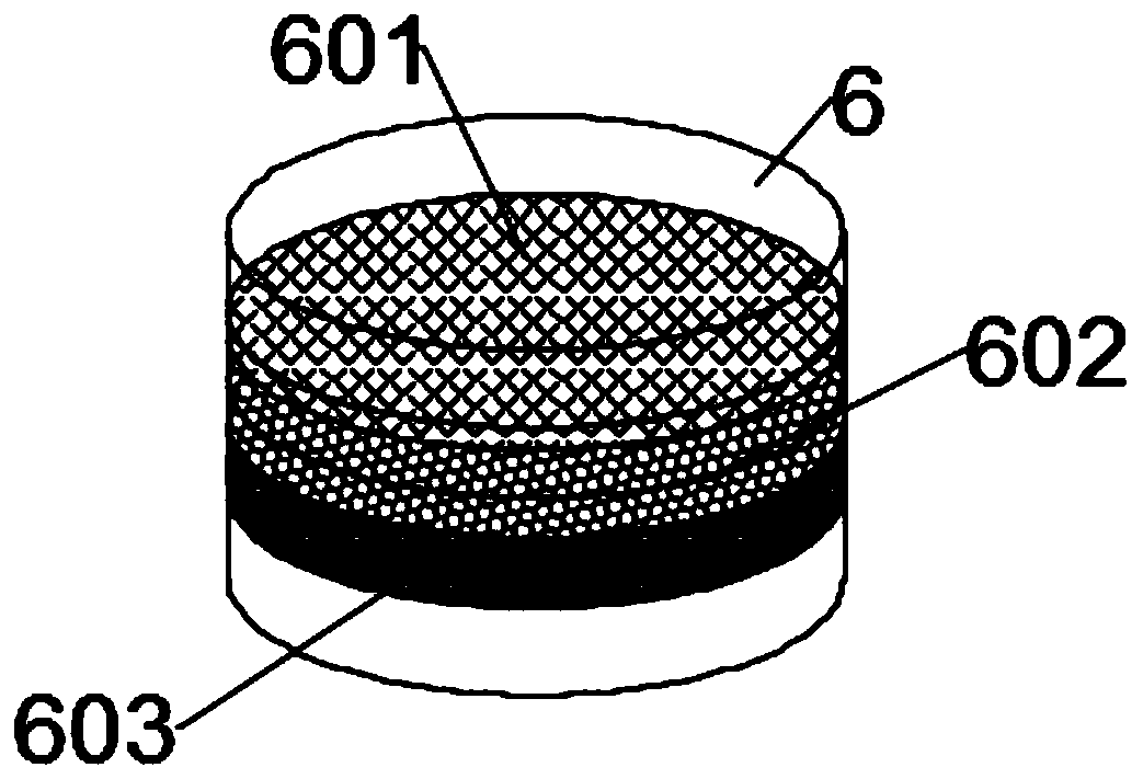
[0026] Such as figure 1 As shown, the embodiment of the present invention provides a tubular heat exchanger, which includes a tube shell 1, and the tube shell 1 is respectively connected with a heat flow inlet 5, a heat flow outlet 7, a cold flow inlet 8 and a cold flow outlet 9. The heat inflow inlet 5 and the heat outflow outlet 7 are connected to the heat exchange assembly inside the tube shell 1; a filter 6 is arranged between the heat inflow inlet 5 and the tube shell 1, and a clean filter 6 is arranged inside the filter 6. water components.

[0027] In this tubular heat exchanger, the heat flow enters the inside of the tube shell 1 through the heat flow inlet 5, flows in the heat exchange assembly, and finally flows out from the heat flow outlet 7, and the cold flow enters the inside of the tube shell 1 through the cold flow inlet 8. The outer side of the hot component flows, exchanges heat with the heat flow inside the heat exchange component, and finally flows out fro...

Embodiment 2

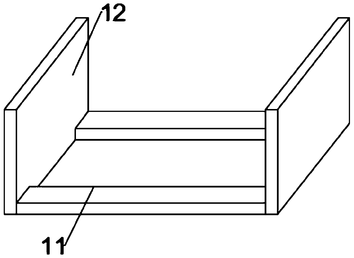
[0035] Such as figure 1 with figure 2 As shown, in another embodiment provided by the present invention, the tube case 1 is rotatably installed in two symmetrically arranged support plates 12, and the bottoms of the support plates 12 are connected by the bottom plate 11; the bottom of the bottom plate 11 Mounted with moving and stabilizing components.

[0036] The heat exchanger is provided with a bottom plate 11 and a support plate 12. Under the action of the bottom plate 11 and the support plate 12, the angular position of the heat exchanger can be adjusted according to specific conditions, and the transfer and installation are facilitated by the moving component and the stabilizing component. , which improves the practicability of the heat exchanger.

[0037] Further, a motor 13 is mounted on the side wall of the support plate 12, the output end of the motor 13 is driven and connected to the rotating shaft 14 through a coupling, and the other end of the rotating shaft 14...


PUM


Abstract

The invention is applicable to the technical field of heat exchangers, and provides a tubular heat exchanger. The tubular heat exchanger comprises a tube shell, wherein a heat flow inlet, a heat flowoutlet, a cold flow inlet and a cold flow outlet are connected to the tube shell respectively, and the heat flow inlet and the heat flow outlet are connected with a heat exchange assembly in the tubeshell; and a filter is arranged between the heat flow inlet and the tube shell, and a water purification assembly is arranged in the filter. Heat flow enters the tube shell through the heat flow inletand flows in the heat exchange assembly, and cold flow enters the tube shell through the cold flow inlet and flows on the outer side of the heat exchange assembly to perform heat exchange with the heat flow in the heat exchange assembly, so that the purpose of heat exchange is achieved; and meanwhile, in order to the solve the problem that water scale is easily produced when hot water enters theheat exchange assembly from the filter and flows, the filter is particularly arranged, the problem about water quality is solved fundamentally by the water purification assembly in the filter, the probability of water scale production is reduced, and therefore, the trouble caused by cleaning of the heat exchange assembly is avoided.

Description

technical field [0001] The invention belongs to the technical field of heat exchangers, in particular to a tube heat exchanger. Background technique [0002] Tubular heat exchanger is the most typical spaced heat exchanger, which is mainly composed of shell, tube bundle, tube sheet and head. It has a long history of industrial application and is the most commonly used in the existing technology. One of the heat exchangers. [0003] There are two fluids for heat exchange in the tube heat exchanger, one flows in the tube and the other flows outside the tube. Through the temperature difference between the two fluids, heat exchange can be performed while flowing to achieve heat exchange. Purpose. [0004] However, the tubular heat exchanger in the prior art will scale in the tube and shell after long-term use, and due to the special shape of the tubular heat exchanger, it is difficult to dismantle and clean, and the thickened scale will not only affect the heat exchange effect...

Claims


Application Information

Patent Timeline
Patent Type & Authority Applications(China)
IPC IPC(8): F28D7/06F28F9/007F28F9/24F28F19/01C02F9/02
CPCC02F1/001C02F1/444C02F9/00F28D7/06F28F9/007F28F9/24F28F19/01
Inventor 范建鹏赵家伟李静楠陈凯
Owner 宁夏绿源实业有限公司
Learn More