
Electronic equipment and control method

A technology of electronic equipment and control method, applied in the field of communication, can solve the problems of small operation, covering the dial, inconvenience and so on

Active Publication Date: 2020-06-26
VIVO MOBILE COMM CO LTD
View PDF11 Cites 4 Cited by
  • Summary
  • Abstract
  • Description
  • Claims
  • Application Information

AI Technical Summary

Problems solved by technology

[0004] The embodiment of the present invention provides an electronic device and a control method to solve the problem that the dial is blocked by fingers during the operation of the existing scheme and the operation is inconvenient due to the small size of the dial

Method used


Image

  • Electronic equipment and control method
  • Electronic equipment and control method
  • Electronic equipment and control method

Examples


Embodiment Construction

[0022] In order to make the technical problems, technical solutions and advantages to be solved by the present invention clearer, the following will describe in detail with reference to the drawings and specific embodiments.

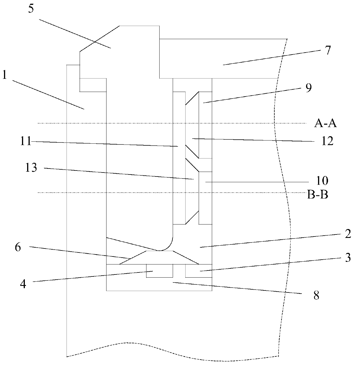
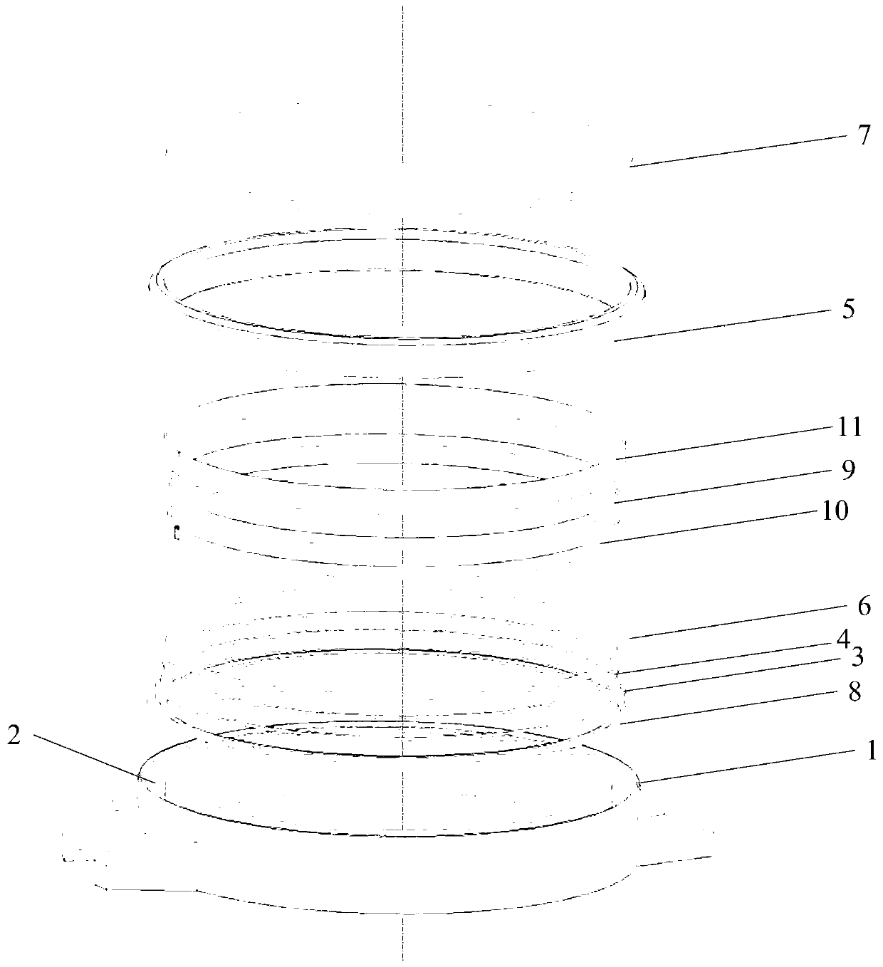
[0023] Such as figure 1 , figure 2 As shown, an electronic device according to an embodiment of the present invention includes:

[0024] A casing 1 having an accommodating space, the casing 1 is provided with a groove 2 around the accommodating space, and a first electrode 3 and a second electrode 4 are arranged on the bottom surface of the groove 2;

[0025] A bezel 5, at least a part of the bezel 5 is set in the groove 2; wherein,

[0026] When the bezel 5 is at the first position of the groove 2, the first electrode 3 and the second electrode 4 are connected; when the bezel 5 is at the first position of the groove 2 In the case of two positions, the first electrode 3 and the second electrode 4 are disconnected.

[0027] In this way, the user can ...


PUM


Abstract

The invention provides electronic equipment and a control method, and relates to the technical field of communication. The electronic equipment comprises a shell with an accommodating space, wherein the shell is provided with a groove around the accommodating space, and the bottom surface of the groove is provided with a first electrode and a second electrode; a watch frame, wherein at least one part of the watch frame is arranged in the groove. When the watch frame is located at the first position of the groove, the first electrode and the second electrode are conducted; under the condition that the watch frame is located at the second position of the groove, the first electrode and the second electrode are disconnected. The scheme of the invention is used for solving the problem that theoperation is inconvenient because the dial plate is small in size because the finger shields the dial plate during the operation of the existing scheme.

Description

technical field [0001] The invention relates to the field of communication technology, in particular to an electronic device and a control method. Background technique [0002] Currently, smart watches are widely used. In the practical application of smart watches, in order to better improve the experience effect of human-computer interaction, a touch display screen is usually integrated on the smart watch. [0003] However, in practice, it has been found that when the user directly operates the touch display with a finger, the touch display may easily cause part of its display area to be blocked by the finger due to its small size, so that the user cannot intuitively view the blocked part of the display area. , for example, the first operation of using a smart watch is to unlock the operation. The user performs the unlocking operation on the touch display screen with a finger. Because of its small size, it is easy to cause part of the display area to be blocked by the fing...

Claims


Application Information

Patent Timeline
IPC IPC(8): G04G17/06G04G17/08G04G21/08
CPCG04G17/06G04G17/08G04G21/08G04C3/007G04G21/02G06F1/163G04G99/006G04G17/045G09G5/10
Inventor 郭远明
Owner VIVO MOBILE COMM CO LTD
Learn More