
Circuit breaker and its operating mechanism

An operating mechanism and circuit breaker technology, which is applied in the protection switch operation/release mechanism, circuit, switchgear status indication, etc., can solve the problems of many parts, many operating mechanism parts, and high difficulty in circuit breaker assembly.

Active Publication Date: 2022-05-06
TIANJIN PINGGAO INTELLIGENT ELECTRIC +2
View PDF10 Cites 0 Cited by
  • Summary
  • Abstract
  • Description
  • Claims
  • Application Information

AI Technical Summary

Problems solved by technology

[0005] The object of the present invention is to provide an operating mechanism to solve the problem of many parts and complicated structure of the operating mechanism in the prior art; the present invention also provides a circuit breaker using the operating mechanism to solve the current There are many problems in the operating mechanism of the circuit breaker in the art, and the structure is complicated, which makes the assembly of the circuit breaker difficult

Method used


Image

  • Circuit breaker and its operating mechanism
  • Circuit breaker and its operating mechanism
  • Circuit breaker and its operating mechanism

Examples


Embodiment 2

[0040] The difference between Embodiment 2 of the circuit breaker of the present invention and Embodiment 1 is that in Embodiment 1, the first crank arm and the second crank arm are integrally arranged. In this embodiment, the first crank arm and the second crank arm are respectively The independent stop is assembled on the drive shaft of the auxiliary switch.

Embodiment 3

[0041] Embodiment 3 of the circuit breaker of the present invention differs from Embodiment 1 in that: in Embodiment 1, the driving arm on the sign is arranged between two mounting plates, and the second arm on the auxiliary switch is arranged on the mounting plate On the outside of the indicator board, the driving link of the sign straddles the mounting plate and connects with the second crank arm and the driving crank arm. In this embodiment, the driving crank arm and the second crank arm on the sign are arranged outside the mounting plate. The sign driving link is connected between the second crank arm and the driving crank arm and is located on the outside of the mounting plate.

Embodiment 4

[0042] The difference between Embodiment 4 of the circuit breaker of the present invention and Embodiment 1 is that the support arm and the vertical plate of the sign in Embodiment 1 are integrally formed and arranged. In this embodiment, the support arm and the vertical plate are arranged separately to support The arm and the vertical plate are connected through a connecting rod transmission.

[0043] The specific structure of the embodiment of the operating mechanism of the present invention is the same as the specific structure of the operating mechanism in any embodiment of the circuit breaker above, and will not be repeated here.


PUM


Abstract

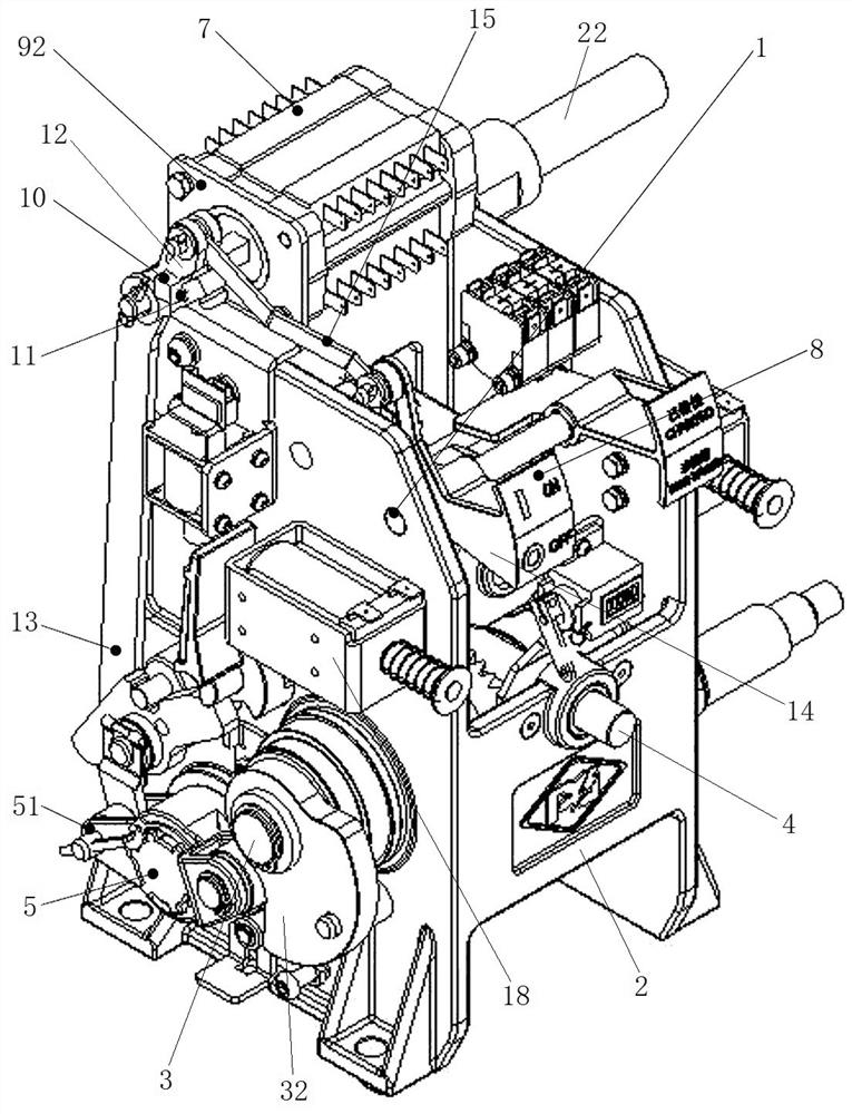
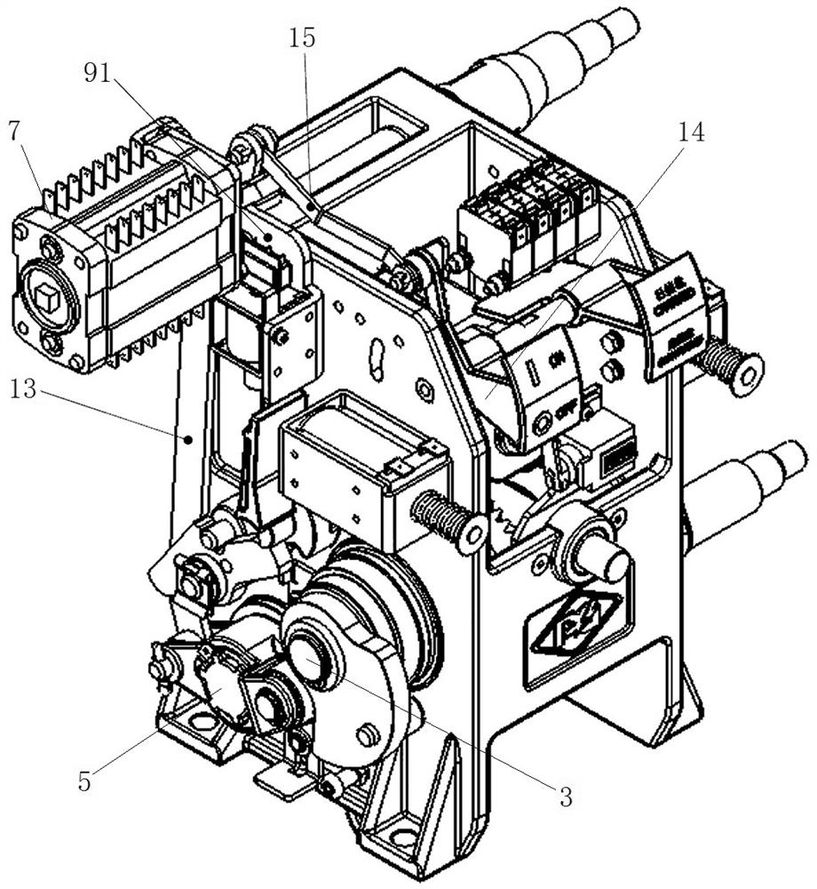
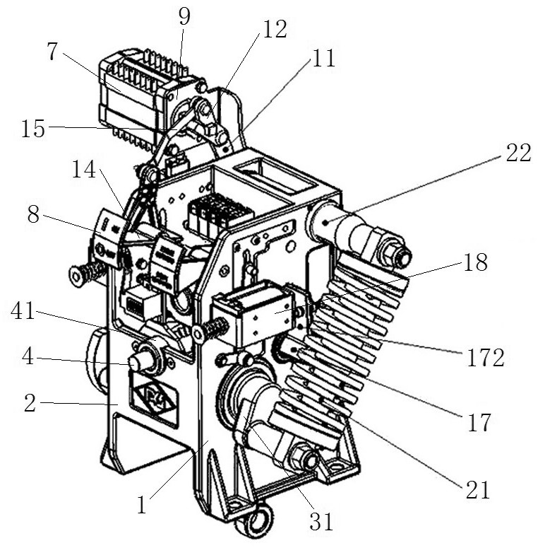
The invention relates to a circuit breaker and its operating mechanism. The circuit breaker includes an arc extinguishing chamber with a moving contact and an operating mechanism connected with the moving contact in the arc extinguishing chamber. The operating mechanism includes a main body frame, on which an output shaft and an auxiliary switch are arranged. The mechanism also includes an indicator plate that is swingably mounted on the main body frame to indicate the working state of the operating mechanism, the output shaft is provided with an output crank arm, and the auxiliary switch has a drive shaft for realizing the auxiliary switch action. The drive shaft is provided with a first crank arm and a second crank arm, and an auxiliary switch driving link is hinged between the output crank arm and the first crank arm; the indicator board is correspondingly provided with a driving crank arm for driving the indicator board action , there is an indicator drive connecting rod hinged between the driving crank arm and the second crank arm. The state switching of the auxiliary switch and the indicator board is realized through a set of link mechanism, which reduces the number of parts of the operating mechanism and is easy to assemble.

Description

technical field [0001] The invention relates to a circuit breaker and its operating mechanism. Background technique [0002] In high-voltage and extra-high-voltage transmission lines, circuit breakers are important equipment to ensure the normal and safe operation of the circuit, and are of great significance to the normal operation of the protection equipment and the personal safety of operators. The operating mechanism is the key component of the circuit breaker, and the operator uses the operating mechanism to realize the opening and closing operation of the circuit breaker. [0003] The operating mechanism of the existing circuit breaker usually includes a main frame. The main frame is provided with an output shaft connected to the opening spring to output the opening power. The output shaft is connected to the moving contact of the circuit breaker through a transmission link to drive the opening. Device opening and closing operation. The main frame is usually also pro...

Claims


Application Information

Patent Timeline
Patent Type & Authority Patents(China)
IPC IPC(8): H01H71/10H01H71/04
CPCH01H71/10H01H71/04H01H2071/046
Inventor 李建兵孙立强齐辉王小焕于洪宇张敬涛薛雯闫姿姿侯小默薛玉栋马雪飞
Owner TIANJIN PINGGAO INTELLIGENT ELECTRIC
Learn More