Supercharge Your Innovation With Domain-Expert AI Agents!

Adhesive based mounting structure

A technology for installing structures and adhesives, applied in the direction of connecting components, material gluing, suction cups, etc., can solve the problems of reducing the optimal bonding strength and excessive use of adhesives

Pending Publication Date: 2020-06-26
CATERPILLAR INC
View PDF8 Cites 0 Cited by
  • Summary
  • Abstract
  • Description
  • Claims
  • Application Information

AI Technical Summary

Problems solved by technology

However, existing adhesive mounting structures have certain drawbacks such as reduced optimal bond strength and excessive use of adhesive

Method used


Image

  • Adhesive based mounting structure
  • Adhesive based mounting structure
  • Adhesive based mounting structure

Examples


Embodiment Construction

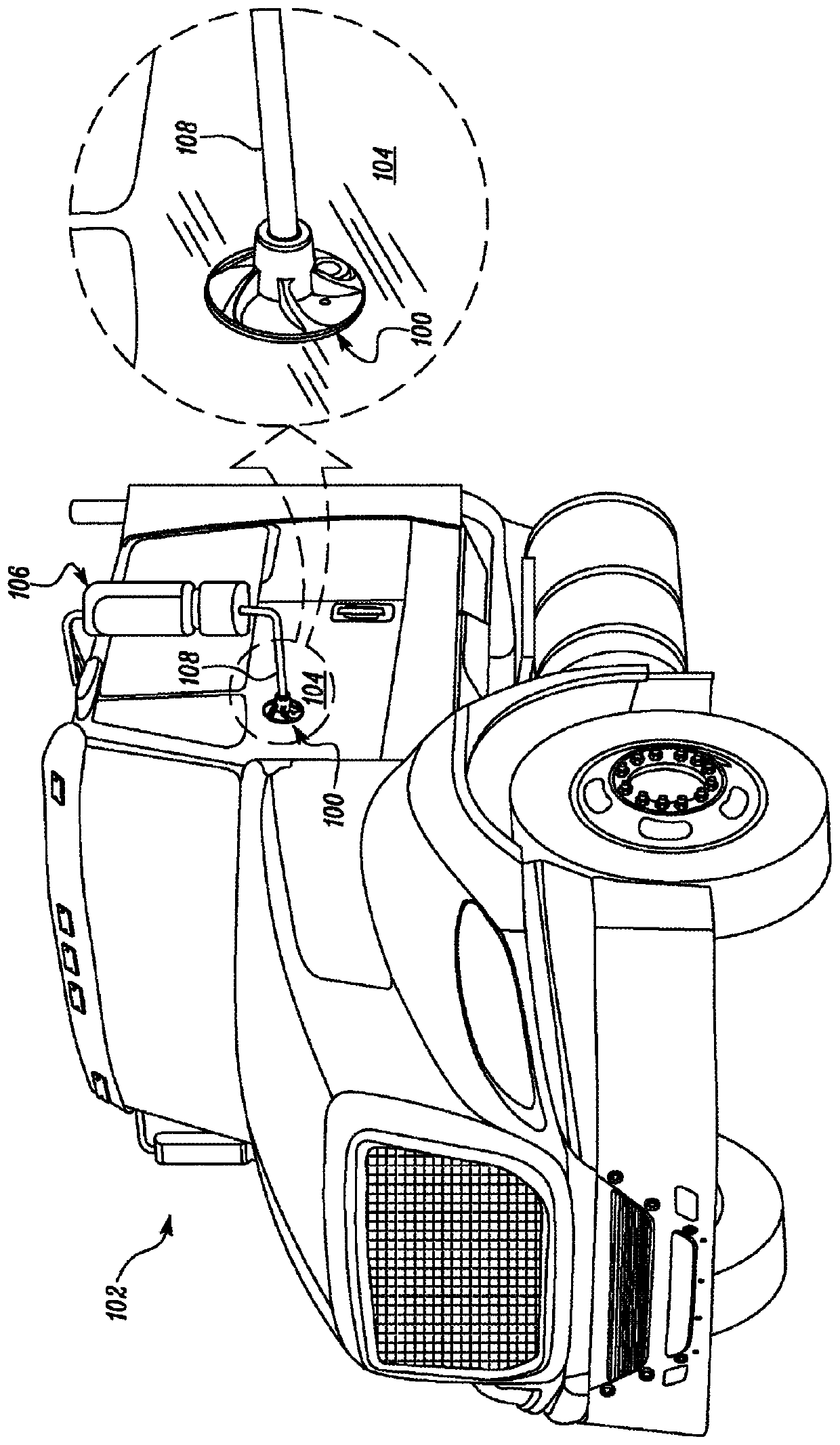
[0023] The present disclosure relates to a mounting structure for adhesively bonding to a surface. figure 1 An exemplary mounting structure 100 is shown attached to a machine 102 in accordance with an embodiment of the present disclosure. Machine 102 is embodied as a truck. However, in various other embodiments, the machine 102 may be any other type of mobile or stationary machine having application in any of earthmoving, mining, construction, railroad, automotive, aerospace, marine, or many other industries . In the illustrated embodiment, the mounting structure 100 is attached to a gate surface 104 (hereinafter surface 104 ) of a machine 102 and supports a component 106 , such as a side mirror. Surface 104 may be any surface and is contemplated including, but not limited to, exterior or interior surfaces associated with machine 102 or any subsystem of machine 102 .

[0024] Component 106 may be supported on mounting structure 100 via attachment hardware 108 associated wit...


PUM


Abstract

A mounting structure (100) for adhesively bonding onto a surface (104) includes a base (110), an outer face (112) of the base (110) and an inner face (114) of the base (110). An adhesive injection port (128) is provided on the outer face (112) of the base (110) for supplying an adhesive. A primary adhesive flow path (134) is provided on the inner face (114) of the base (110). The primary adhesiveflow path (134) is in fluid communication with the adhesive injection port (128) and allows the adhesive to flow. Further, a plurality of secondary adhesive flow paths (146) originating from the primary adhesive flow path (134) allow the adhesive to distribute on the inner face (114).

Description

technical field [0001] The present disclosure relates generally to mounting structures for adhesively bonding to a surface, and more particularly to mounting structures having adhesive flow paths for distributing a flow of adhesive for bonding to a surface. Background technique [0002] In many industrial applications, it may be advantageous to mount or attach components such as electrical wiring harnesses, hydraulic wiring harnesses, small hardware, displays, side view mirrors, etc. to a support structure by adhesively connecting the mounting structure. For example, it may be necessary to attach hardware to the underlying structure in the machine, such as a Roll Over Protective Structure (ROPS), or directly to an existing panel, such as a body panel. In conventional systems, the hardware is usually attached to the structure using welding techniques. However, welding is often necessary during initial machine assembly and may not be a viable option for end-of-line installati...

Claims


Application Information

Patent Timeline
IPC IPC(8): F16B47/00F16B11/00
CPCF16B47/003F16B11/006
Inventor J·A·延森J·J·埃夫里A·K·阿姆斯特茨S·D·伦德奎斯特
Owner CATERPILLAR INC
Features
  • R&D
  • Intellectual Property
  • Life Sciences
  • Materials
  • Tech Scout
  • Unparalleled Data Quality
  • Higher Quality Content
  • 60% Fewer Hallucinations
Learn More