
Method for determining dynamic range of interferometer during spherical defocusing detection

A dynamic range, defocus detection technology, applied in the field of optical instruments and optical detection, to achieve the effect of a wide range of applications, a simple method, and a reliable theory

Active Publication Date: 2020-06-30
NANTONG UNIVERSITY
View PDF14 Cites 1 Cited by
  • Summary
  • Abstract
  • Description
  • Claims
  • Application Information

AI Technical Summary

Problems solved by technology

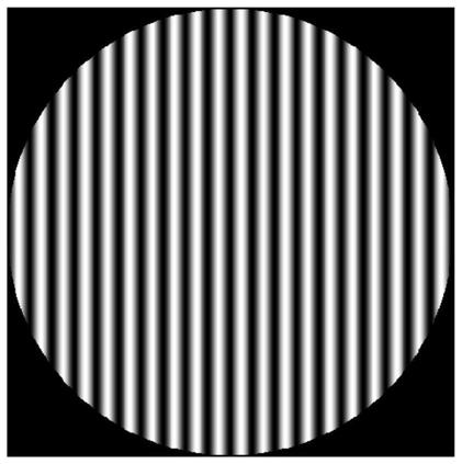
The number of resolvable fringes mentioned in the instructions of some interferometers is only straight fringes with equal intervals, and there is no mention of the interference ring

Method used


Image

  • Method for determining dynamic range of interferometer during spherical defocusing detection
  • Method for determining dynamic range of interferometer during spherical defocusing detection
  • Method for determining dynamic range of interferometer during spherical defocusing detection

Examples


Embodiment Construction

[0025] In order to make the technical problems, technical solutions and advantages to be solved by the present invention clearer, the following will describe in detail with reference to the drawings and specific embodiments.

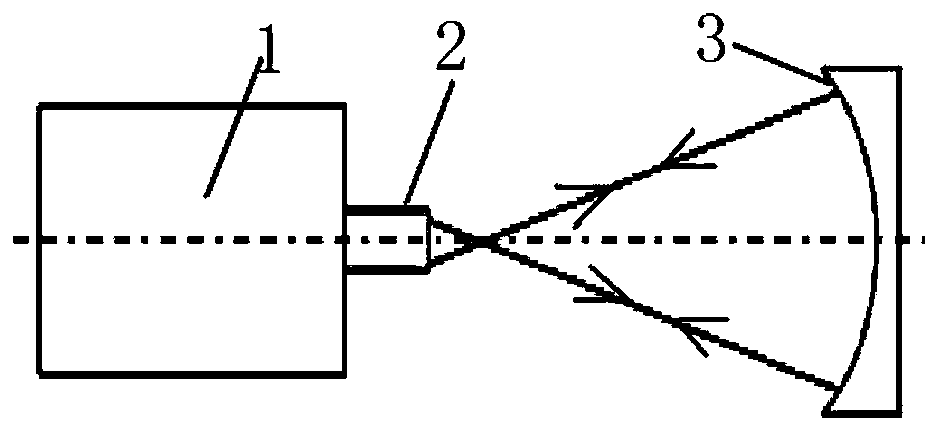
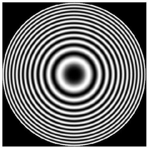
[0026] When the spherical surface is defocused for interference detection, the interference fringes are concentric rings, and the interferogram is just not enough for the entire detector. The maximum wave aberration value or the maximum number of rings when the detector is completely sampled is the value of the interferometer when the spherical surface is defocused. Dynamic Range. Based on this, the present invention provides a method for determining the dynamic range of the interferometer during spherical defocus detection. The dynamic range of the interferometer during spherical defocus detection refers to: the maximum wave aberration value or the most circular ring when the detector is completely sampled Number, to determine the dynamic range of the i...


PUM


Abstract

The invention provides a method for determining the dynamic range of an interferometer during spherical defocusing detection, and the dynamic range of the interferometer during spherical defocusing detection refers to the maximum wave aberration value or the maximum number of rings during complete sampling of a detector, and the determination of the dynamic range of the interferometer during spherical defocusing detection is the determination of the complete sampling of the detector. The complete sampling requirement of the detector is as follows: the interference pattern can be completely distinguished by the detector, and the wave aberration corresponding to one interference fringe at the densest interference fringe on the interference pattern is equal to the wave aberration corresponding to the Nyquist frequency of the detector. According to the invention, the lack of a method for determining the dynamic range of the interferometer during spherical out-of-focus measurement is made up, and the performance index of the interferometer is perfected. The method is reliable in theory, simple, accurate in judgment and wide in application range.

Description

technical field [0001] The invention belongs to the technical field of optical instruments and optical detection, and in particular relates to a method for determining the dynamic range of an interferometer in spherical defocus detection. Background technique [0002] According to the principle of superposition, the result of wave merging has the property of reflecting the original state of waves. When two beams of light with the same frequency are superimposed, the fringes they produce depend on their phase difference: a strengthening fringe (or ring) is produced when the phase is the same, a weakening fringe is produced when the opposite is the case, and an intermediate is produced between the two cases. Intensity fringes, the resulting interference fringes can reflect the optical path difference of the two beams of light. An interferometer is an instrument that obtains measurement information based on the interference phenomenon caused by the superposition of waves. It i...

Claims


Application Information

Patent Timeline
Patent Type & Authority Applications(China)
IPC IPC(8): G01B9/02G01B11/24
CPCG01B9/02G01B11/2441
Inventor 潘宝珠汤靖王雪莹方靖淮姜舒昊仲崇贵纪宪明
Owner NANTONG UNIVERSITY
Learn More