A transmittance adjustment device

An adjustment device and technology of transmittance, applied in optical elements, instruments, optics, etc., can solve the problems of upper limit limit of transmittance adjustment and inability to achieve continuous adjustment of transmittance.

Active Publication Date: 2021-10-22
SHANGHAI MICRO ELECTRONICS EQUIP (GRP) CO LTD
View PDF3 Cites 0 Cited by
  • Summary
  • Abstract
  • Description
  • Claims
  • Application Information

AI Technical Summary

Problems solved by technology

[0005] The embodiment of the present invention provides a transmittance adjustment device to solve the problem that the upper limit of the transmittance adjustment of the existing mechanical transmittance adjustment device is limited, and the continuous adjustment of the transmittance cannot be realized.

Method used


Image

  • A transmittance adjustment device
  • A transmittance adjustment device
  • A transmittance adjustment device

Examples


Embodiment Construction

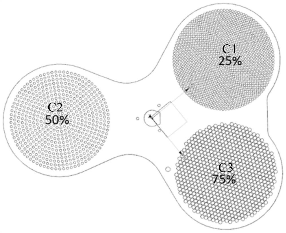
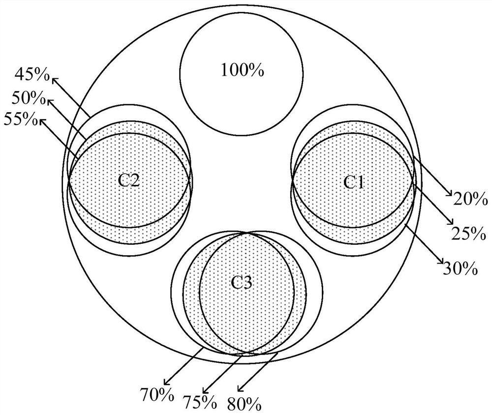
[0033] The present invention will be further described in detail below in conjunction with the accompanying drawings and embodiments. It should be understood that the specific embodiments described here are only used to explain the present invention, but not to limit the present invention. In addition, it should be noted that, for the convenience of description, only some structures related to the present invention are shown in the drawings but not all structures.

[0034] As a part of the optical system, the transmittance adjustment device needs to maintain the static uniformity, integral uniformity and pupil uniformity of the optical system while realizing the transmittance adjustment. Static uniformity refers to the uniform change of the transmittance of the light source after the transmittance adjustment device is rotated by a certain angle. The integral uniformity refers to the uniform change of the multiple rate of increase or decrease of the transmittance after the tran...


PUM


Abstract

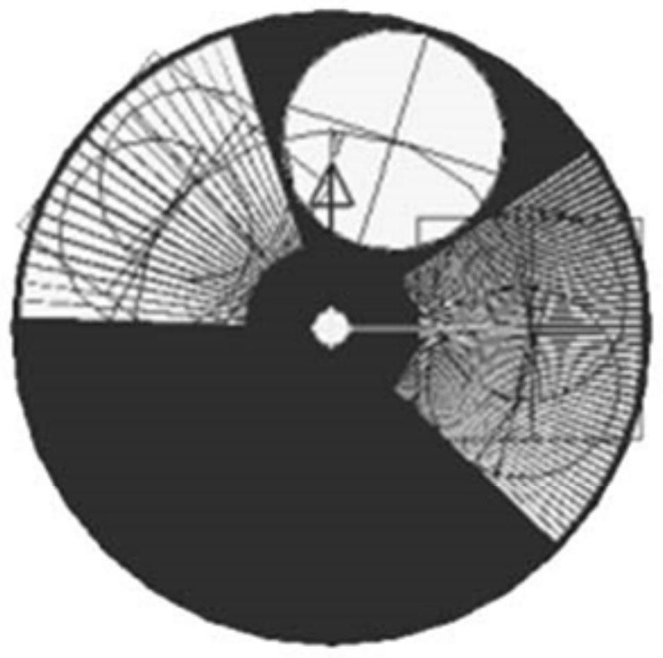
The invention discloses a transmittance adjustment device, comprising: a rotation center area, and an annular structure arranged around the rotation center area; the ring structure includes a transmittance adjustment area and a completely light-transmitting area; the transmittance adjustment area is perpendicular to the rotation The first side in the axial direction of the central area is connected to the third side of the fully transparent area perpendicular to the axial direction of the central area of ​​rotation; the second side of the transmittance adjustment area perpendicular to the axial direction of the central area of ​​rotation is connected to the fully transparent area The fourth side perpendicular to the axis of the rotation center area is connected; the transmittance adjustment area is provided with light transmission holes arranged in an array, and the light transmission area of ​​the transmittance adjustment area is in the clockwise or counterclockwise direction around the rotation center area. direction gradually increases. The invention provides a transmittance adjustment device to solve the problem that the upper limit of the transmittance adjustment of the existing mechanical transmittance adjustment device is limited, and the continuous adjustment of the transmittance cannot be realized.

Description

technical field [0001] The invention relates to the field of illumination technology, in particular to a transmittance adjustment device. Background technique [0002] For an illumination system in the form of dual light sources or multiple light sources, there are certain differences in the optical power of different light sources under the same power. For example, if the light source is a mercury lamp, for an illumination system with multiple mercury lamps, there is a difference of about 2% in the light power of different mercury lamps at the same power. When the optical power deviates, it is necessary to adjust the light source power to make the optical power of each light source consistent. However, this method is costly, complicated to operate, and takes a long time. Therefore, a transmittance adjustment device is often added to the lighting system to adjust the light emitted by the lighting system to obtain more uniform lighting conditions. [0003] The transmittanc...

Claims


Application Information

Patent Timeline
Patent Type & Authority Patents(China)
IPC IPC(8): G02B26/04
CPCG02B26/04
Inventor 赵仁洁侯宝路湛宾洲胡小林吴飞
Owner SHANGHAI MICRO ELECTRONICS EQUIP (GRP) CO LTD
Why Eureka
Try Eureka