
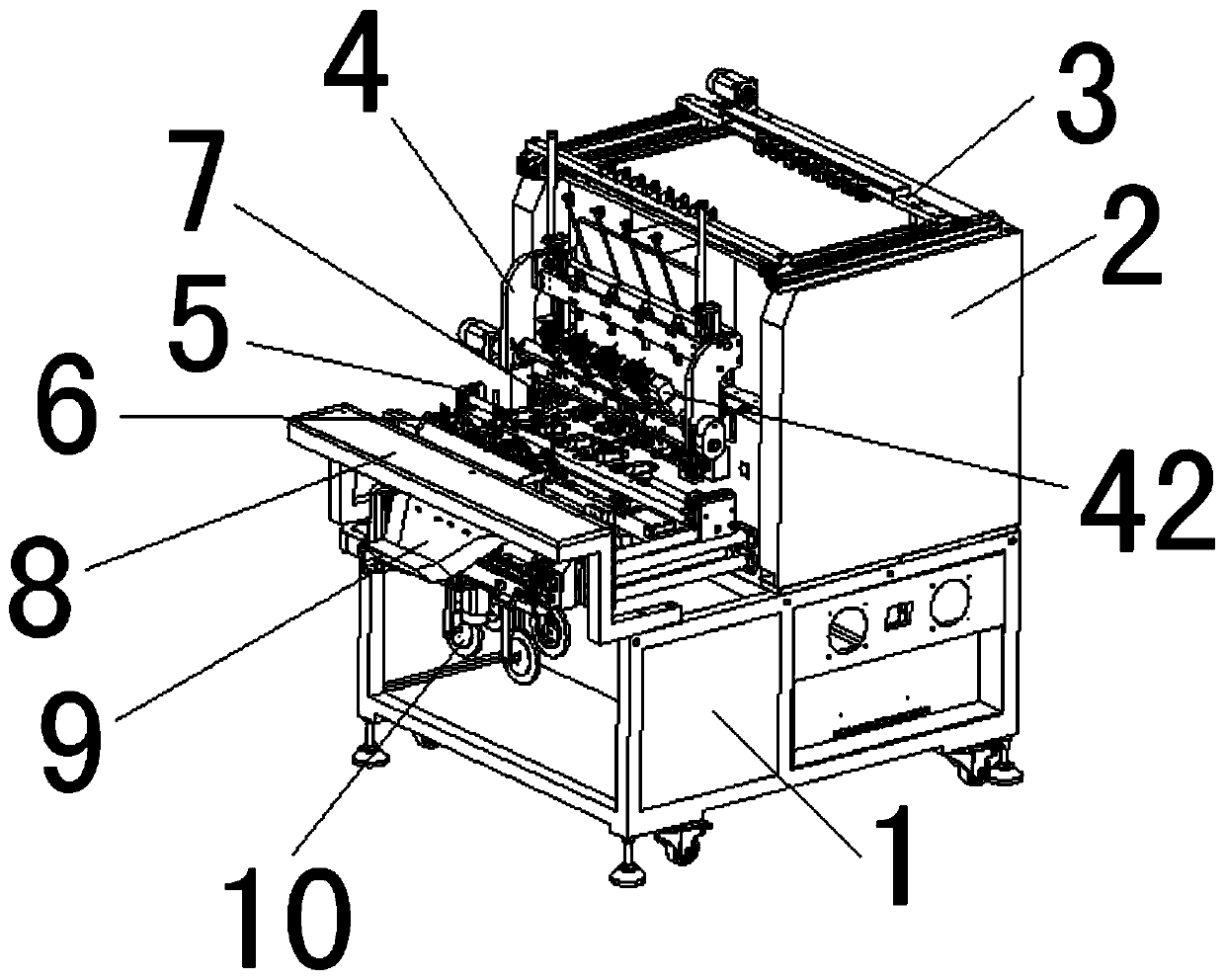
Automatic sleeve penetrating winding machine

A technology of automatic casing threading and winding machine, which is used in coil manufacturing, electrical components, inductor/transformer/magnet manufacturing, etc. High winding efficiency and good winding effect

Active Publication Date: 2020-06-30
东莞市纵易智能装备有限公司
View PDF22 Cites 12 Cited by
  • Summary
  • Abstract
  • Description
  • Claims
  • Application Information

AI Technical Summary

Problems solved by technology

[0003] The technical problem to be solved by the present invention is to provide an automatic casing threading and winding machine. Cut the tube into sections, store the sleeve, attenuate the tension of the wire, push the beginning of the sleeve to wrap the PIN foot, wind the skeleton, make a right-angle shaping at the end of the winding of the skeleton, push the end of the sleeve to wrap the PIN foot, wrap the skeleton and finish the product A series of operations such as blanking not only solve the problems of low efficiency, high labor intensity of workers and high labor cost of enterprises in the traditional manual operation of casing threading, but also solve the current problem of casing transportation. Due to the imperfect structural design of the mechanism, the casing is often flattened and deformed, resulting in unsmooth feeding of the casing and the inability to automatically load the skeleton and thread the casing on one piece of equipment. According to the needs of production, the Sleeve cutting into sections, storing the sleeve, attenuating the tension of the wire, pushing the beginning of the sleeve to wrap the PIN pin, winding the skeleton, making a right-angle shaping at the end of the winding of the skeleton, pushing the end of the casing to wrap the PIN foot, wrapping the skeleton and the finished product A series of operations such as blanking lead to the need to purchase multiple equipment to meet production requirements

Method used


Image

  • Automatic sleeve penetrating winding machine
  • Automatic sleeve penetrating winding machine
  • Automatic sleeve penetrating winding machine

Examples


Embodiment Construction

[0038] In order to facilitate the understanding of the present invention, the present invention will be described more fully below with reference to the associated drawings. Preferred embodiments of the invention are shown in the accompanying drawings. However, the present invention can be embodied in many different forms and is not limited to the embodiments described herein. On the contrary, the purpose of providing these embodiments is to make the disclosure of the present invention more thorough and comprehensive.

[0039] Unless otherwise defined, all technical and scientific terms used herein have the same meaning as commonly understood by one of ordinary skill in the technical field of the invention. The terminology used herein in the description of the present invention is only for the purpose of describing specific embodiments, and is not intended to limit the present invention.

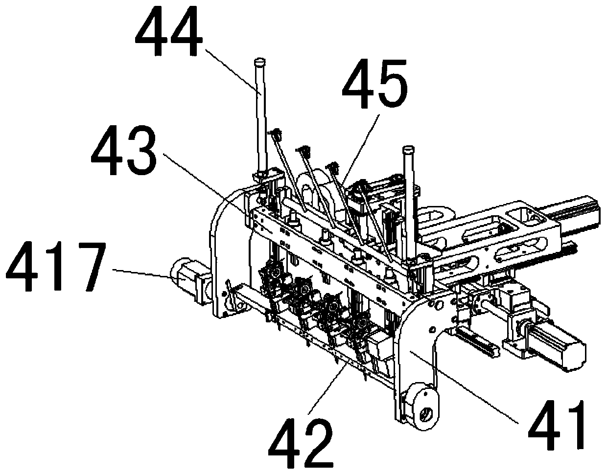
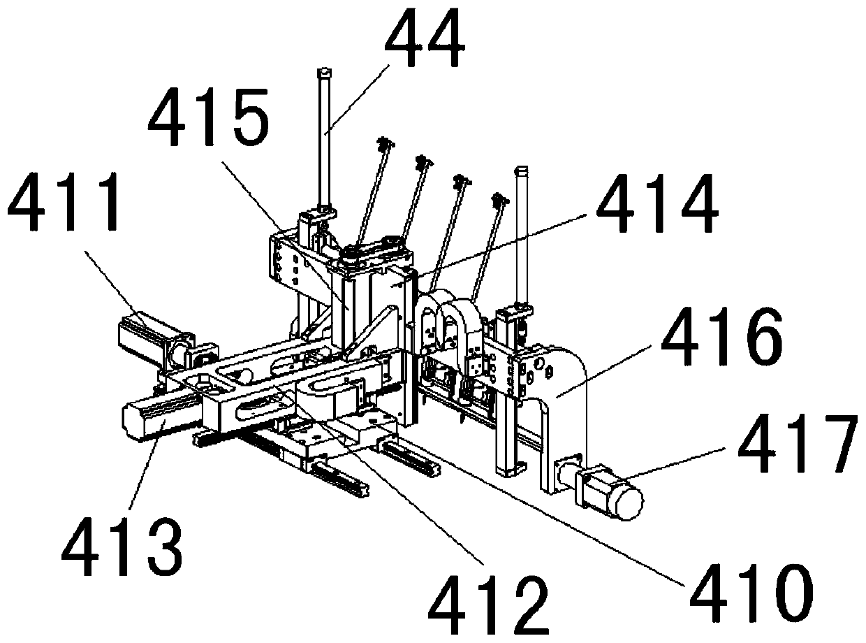
[0040] In this example, refer to Figure 1 to Figure 16As shown, the automatic casing...


PUM


Abstract

The invention discloses an automatic sleeve penetrating winding machine which comprises an attenuation mechanism, a three-axis movement mechanism, a wire clamp mechanism, a feeding mechanism, a discharging mechanism, a rubber coating mechanism and the like. According to the automatic sleeve penetrating winding machine, a framework can be automatically fed on one mechanism; a wire is sleeved with asleeve, the sleeve is cut into sections according to the production requirement, the sleeve is stored, the tension of the wire is attenuated, an initial end of the sleeve is pushed to be wound with aPIN, framework winding is conducted, a tail end of the framework winding is subjected to right-angle shaping, a tail end of the sleeve is pushed to be wound with the PIN, the rubber coating of the framework is conducted, and a finished product is discharged. Therefore, the problems of low efficiency, high labor intensity of workers and high labor cost of enterprises in a traditional manual operation mode for pulling the wire into the sleeve are solved; and the problems that due to the fact that an existing sleeve conveying mechanism is imperfect in structural design, so a sleeve is often flattened and pressed to deform such that the sleeve is not conveyed smoothly, and multiple different procedures cannot be conducted on one mechanism are solved.

Description

technical field [0001] The invention relates to an automatic casing threading and winding machine. Background technique [0002] The winding machine needs to put the wire through the sleeve before proceeding to the winding process. Traditionally, the wire through the sleeve is generally carried out by manual operation. Manual sleeve insertion has low efficiency, poor effect, and labor intensity for workers. Large and high labor costs and other deficiencies. Later, some casing conveying mechanisms appeared on the market. Due to their imperfect structural design, the casing is often crushed or the casing is not smoothly conveyed during the process of conveying and passing through the pipe, which seriously affects its winding efficiency. In addition, the current casing conveying mechanism can only transport the casing, which cannot automatically load the skeleton, thread the wire through the casing, cut the casing into sections according to the production needs, and Store th...

Claims


Application Information

Patent Timeline
IPC IPC(8): H01F41/06H01F41/076H01F41/096H01F41/12
CPCH01F41/06H01F41/127H01F41/076H01F41/096
Inventor 刘世君杨波
Owner 东莞市纵易智能装备有限公司
Learn More