Rotary lock catch structure of dust collector battery pack
A battery pack and rotating technology, which is applied in the installation of vacuum cleaners, electrical equipment, cleaning equipment, etc., can solve the problems of reduced joint degree, wear, and singleness of the buckle and the slot, and achieve the characteristics of not easy to wear and long service life Effect
- Summary
- Abstract
- Description
- Claims
- Application Information
AI Technical Summary
Problems solved by technology
Method used
Image
Examples
Embodiment 1
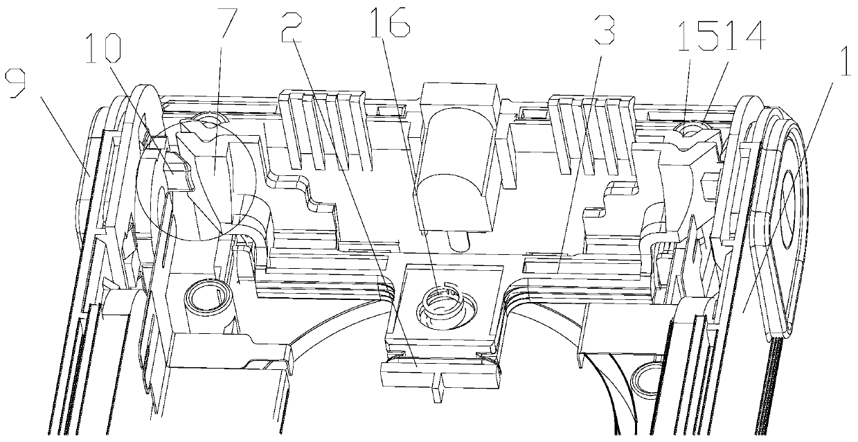
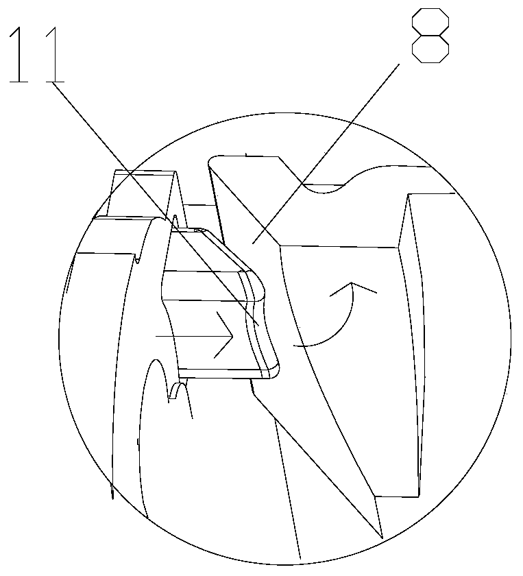
[0026] Please combine figure 1 , figure 2 as well as Figure 5 , a rotary locking structure for a vacuum cleaner battery pack, comprising a battery pack housing 1, a locking mechanism is provided inside the battery pack housing 1, and the locking mechanism includes a buckle 2 and an assembly with the buckle 2 The matching rotating rod 3, the buckle 2 is fixed on the rotating rod 3; the rotating rod 3 is rotatably arranged inside the battery pack housing 1; the battery pack housing 1 is provided with The card slot 4 corresponding to the buckle 2, the battery pack housing 1 is provided with a switch structure acting on the rotating rod 3; the rotating rod 3 is provided with two left-right symmetrical protrusions 7 , the side of the bump 7 is a first slope 8; the switch structure includes two left and right buttons 9 correspondingly arranged, the head of the button 9 is provided with a pressing block 10, and the surface of the pressing block 10 is the same as The second slope...
Embodiment 2
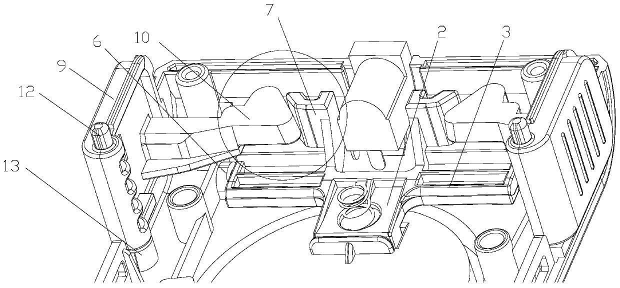
[0029] Please combine image 3 , Figure 4 as well as Figure 5 , a rotary locking structure for a vacuum cleaner battery pack, comprising a battery pack housing 1, a locking mechanism is provided inside the battery pack housing 1, and the locking mechanism includes a buckle 2 and an assembly with the buckle 2 The matching rotating rod 3, the buckle 2 is fixed on the rotating rod 3; the rotating rod 3 is rotatably arranged inside the battery pack housing 1; the bottom of the battery pack housing 1 is provided with The card slot 4 corresponding to the buckle 2, the battery pack housing 1 is provided with a switch structure acting on the rotating rod 3; the rotating rod 3 is provided with two left-right symmetrical protrusions 7 , the side of the bump 7 is a first slope 8; the switch structure includes two left and right buttons 9 correspondingly arranged, the head of the button 9 is provided with a pressing block 10, and the surface of the pressing block 10 is the same as Th...
Embodiment approach
[0032] The fastening part of the buckle 2 is provided with an arc surface; the arc surface can increase the locking force of the entire buckle structure, and due to the rotating structure of the buckle 2, there is no need to worry about the buckle 2 and the slot 4 being stuck together. The situation that it cannot be separated after connection; at the same time, when the bottom shell of the battery pack is in contact with the buckle 2, due to the design of the arc surface, the contact between the two can be made smoother.
[0033] The lock mechanism is specifically an integrated structure composed of the rotating rod 3 and the buckle 2; the rotating rod 3 and the buckle 2 are formed by mold injection molding into an integrated structure, which does not require subsequent assembly and can be used as a battery The installation of the bag improves the portability, and at the same time, the one-piece structure can prevent the buckle 2 from loosening.
[0034] The inner wall of the...
PUM
 Abstract
Description
Claims
Application Information
 - R&D
- Intellectual Property
- Life Sciences
- Materials
- Tech Scout
- Unparalleled Data Quality
- Higher Quality Content
- 60% Fewer Hallucinations
Browse by: Latest US Patents, China's latest patents, Technical Efficacy Thesaurus, Application Domain, Technology Topic, Popular Technical Reports.
© 2025 PatSnap. All rights reserved.Legal|Privacy policy|Modern Slavery Act Transparency Statement|Sitemap|About US| Contact US: help@patsnap.com


