

Mobile position-fixing determination device for electricity meter inspection
A technology for mobile positioning and measuring devices, which is applied in the directions of measuring devices, measuring electrical variables, non-rotating vibration suppression, etc., and can solve problems such as easily damaged electric cards and electric card slot components, staff fatigue, and damage to programming buttons
- Summary
- Abstract
- Description
- Claims
- Application Information
AI Technical Summary
Problems solved by technology
Method used
Image

Examples
Embodiment
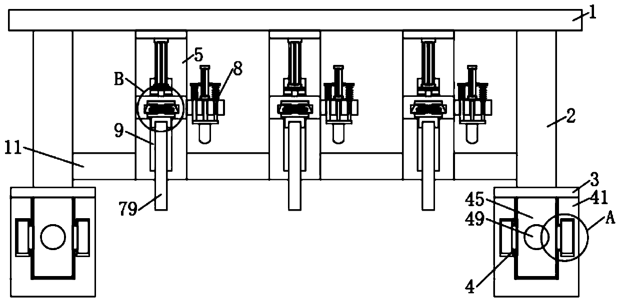
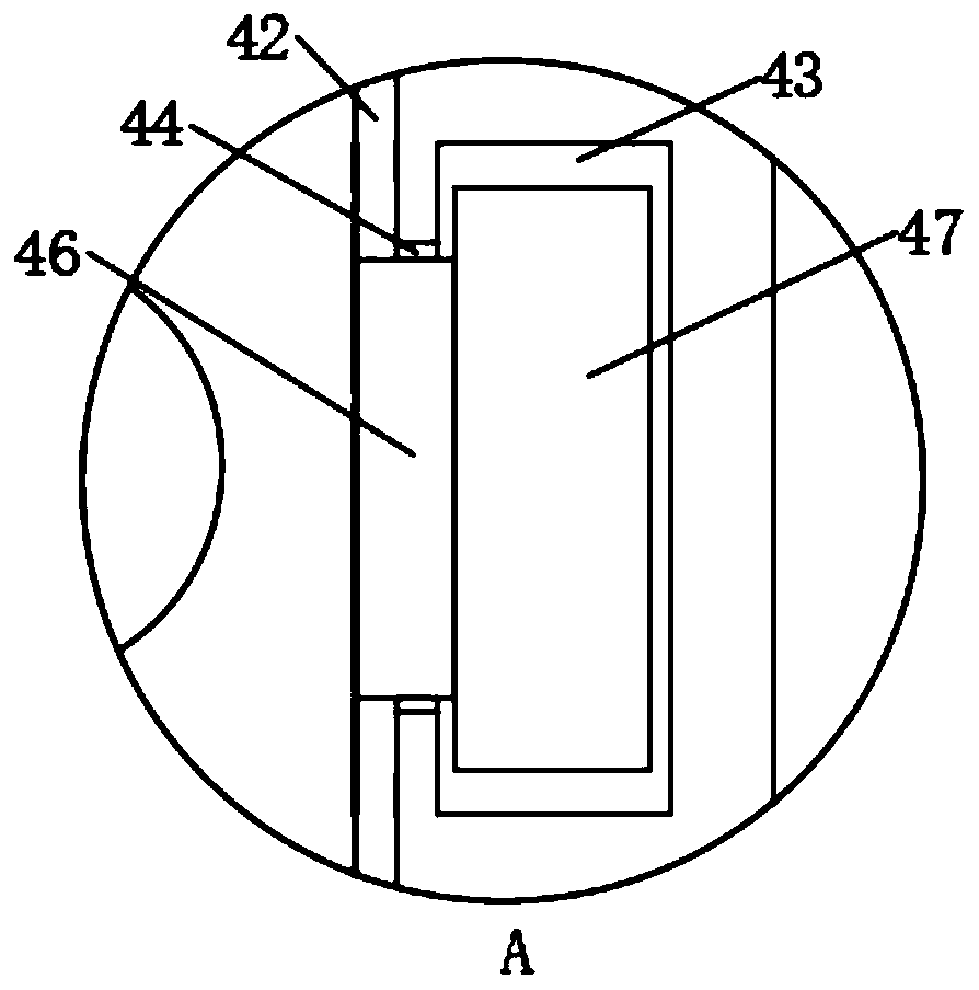
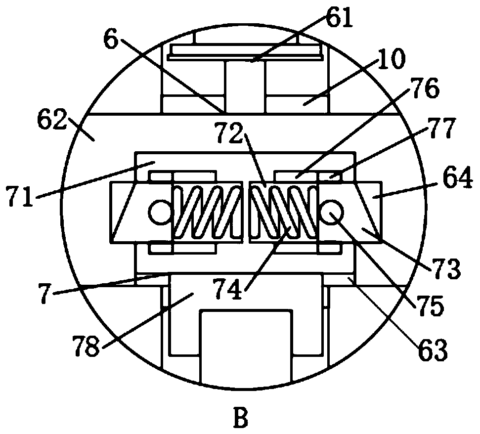
[0026] Example: such as Figure 1-6 As shown, a mobile positioning measuring device for electric energy meter detection in the present invention includes a horizontal plate 1, and both sides of the lower end of the horizontal plate 1 are fixedly connected with support plates 2, and the lower ends of the two support plates 2 are fixedly connected There are seat plates 3, the lower ends of the two seat plates 3 are equipped with sliding seats 4, the lower ends of the horizontal plates 1 are fixedly connected with several mounting plates 5, and some of the mounting plates 5 are in an L-shaped structure, and some of the mounting plates 5 The front of the vertical part of the mounting plate 5 is provided with a third chute 9, the interior of some of the third chute 9 is slidingly connected with a slide plate 10, and the fronts of some of the slide plates 10 are connected with a push-down mechanism 6. The card insertion mechanism 7 and the point pressing mechanism 8 utilize the pres...
PUM
 Abstract
Description
Claims
Application Information