Polyethylene mixing device
A mixing device and polyethylene technology, applied in the field of particle processing, can solve the problems of inflexible and convenient use, poor mixing effect, long process flow, etc., and achieve the effect of improving mixing effect, good mixing effect and convenient use
- Summary
- Abstract
- Description
- Claims
- Application Information
AI Technical Summary
Problems solved by technology
Method used
Image

Examples
Embodiment 1
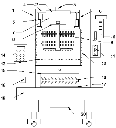
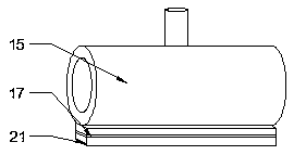
[0023] see Figure 1~3 , in an embodiment of the present invention, a polyethylene mixing device includes a No. 1 mixing box; the No. 1 mixing box is sequentially provided with a heating chamber 12 and a stirring chamber from the outside to the inside; the No. 1 mixing box Fixedly connected to the mounting frame 1; the mounting frame 1 is provided with a control panel 14; the outside of the No. 1 mixing tank is equipped with a water inlet pipe 10 and a heater 11; the inside of the mixing chamber is provided with a No. 1 agitator 9; The top of the No. 1 agitator 9 stretches out the stirring chamber and connects the No. 1 driving box 8; the top of the No. 1 driving box 8 is equipped with an installation box 7; the top of the installation box 7 is equipped with a fixed box 2; An additive inlet 3 is installed on the top of the box 2; a stirring adjustment mechanism is installed on the fixed box 2; the mounting frame 1 is installed on the top of the base 19; a lower box 21 is insta...
Embodiment 2
[0032] see figure 1 , the circulation mechanism can also be installed on the No. 1 mixing box; the circulation mechanism includes a circulation pipe; a booster pump is installed on the circulation pipe; one end of the circulation pipe is arranged on the top of the No. 1 screen 13 and The No. 1 mixing box is connected; the other end of the circulation pipe is arranged under the No. 1 screen 13 and connected to the No. 1 mixing box; the mixing effect can be further improved by setting the circulation mechanism.
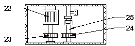
[0033]The working principle of the present invention is: through the setting of the slide bar 4, the electric telescopic rod 5 and the limit rail 6, when the No. 1 agitator 9 is stirring, the height of the No. 1 agitator 9 can be adjusted to improve the stirring effect; The setting of the spring improves the stability of the No. 1 agitator 9 when it moves up and down; through the setting of the additive inlet 3, the fixed box 2, the servo motor 22, the No. 1 gear 23, th...
PUM
 Abstract
Description
Claims
Application Information
 - Generate Ideas
- Intellectual Property
- Life Sciences
- Materials
- Tech Scout
- Unparalleled Data Quality
- Higher Quality Content
- 60% Fewer Hallucinations
Browse by: Latest US Patents, China's latest patents, Technical Efficacy Thesaurus, Application Domain, Technology Topic, Popular Technical Reports.
© 2025 PatSnap. All rights reserved.Legal|Privacy policy|Modern Slavery Act Transparency Statement|Sitemap|About US| Contact US: help@patsnap.com