Mold closing device for injection molding machine and mold closing method of mold closing device

A mold clamping device and injection molding machine technology, which is applied in the field of mold clamping devices for injection molding machines, can solve the problems of complex and inconvenient operation of mold replacement, the inability to completely match the front mold and the rear mold, and affecting the production efficiency of injection molded parts, etc.

Active Publication Date: 2020-07-03
QINGDAO LET FLEXITANK CO LTD
View PDF7 Cites 2 Cited by
  • Summary
  • Abstract
  • Description
  • Claims
  • Application Information

AI Technical Summary

Problems solved by technology

[0004] The object of the present invention is to provide a mold clamping device for injection molding machine and its mold clamping method. For different injection molded parts, the mold needs to be replaced. The existing mold replacement method is complicated and inconvenient to operate, which seriously affects the production efficiency of the injection molded parts. The front mold and the rear mold cannot be completely matched during ...

Method used


Image

  • Mold closing device for injection molding machine and mold closing method of mold closing device
  • Mold closing device for injection molding machine and mold closing method of mold closing device
  • Mold closing device for injection molding machine and mold closing method of mold closing device

Examples


Embodiment Construction

[0032]The technical solutions of the present invention will be clearly and completely described below in conjunction with the embodiments. Apparently, the described embodiments are only some of the embodiments of the present invention, not all of them. Based on the embodiments of the present invention, all other embodiments obtained by persons of ordinary skill in the art without creative efforts fall within the protection scope of the present invention.

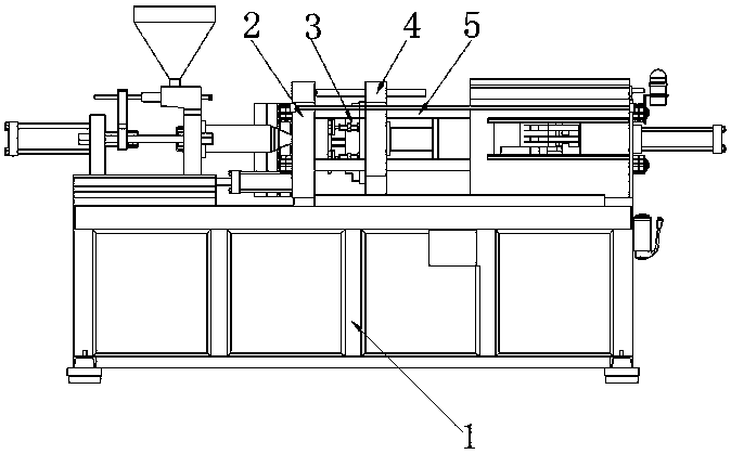
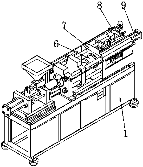
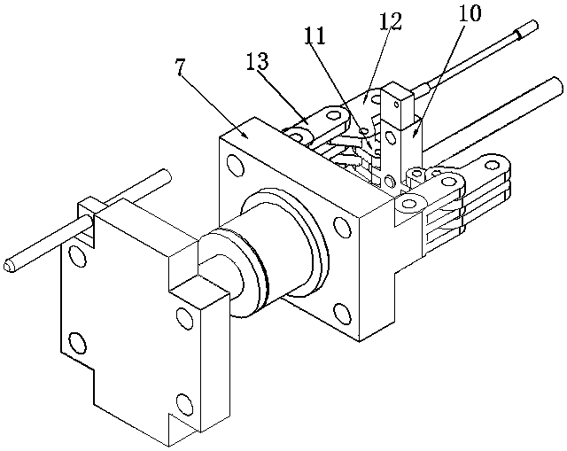
[0033] see Figure 1-7 As shown, a mold clamping device for an injection molding machine includes a chassis 1, a fixing seat 2, a clamping mechanism 3, a sliding seat 4, a sliding rod 5, a pushing seat 6, a buffer connection seat 7 and an installation seat 8, and the chassis 1 One end of the top is installed with a fixed base 2, and the other end of the top of the bottom frame 1 is equipped with a mounting base 8, and a sliding bar 5 is installed around the fixed base 2 and the mounting base 8, and the outer side of the slid...


PUM


Abstract

The invention discloses a mold closing device for an injection molding machine. The mold closing device comprises a bottom frame, a fixed seat, a clamping mechanism, a sliding seat, sliding rods, a push seat, a buffer connecting seat and a mounting seat, wherein the fixed seat is installed at one end of the top of the bottom frame, the mounting seat is installed at the other end of the top of thebottom frame, the sliding rods are installed on the periphery between the fixed seat and the mounting seat, and the sliding seat and the buffer connecting seat are installed on the outer sides of thesliding rods in a sliding mode. According to the mold closing device for the injection molding machine, when a mold is placed on a fixed limiting block and the bottom of the mold makes contact with afixed plate, an induction block is completely compressed into a containing groove at the moment, a second spring is compressed into a telescopic groove, a movable contact at the bottom of a second limiting sliding block makes contact with a fixed contact at the top of a supporting rod at the moment, and electric connection between a storage battery and a PLC is kept; and then a hydraulic pump is controlled by the PLC to clamp the mold, it is guaranteed that the bottom side of the mold makes contact with the fixed seat and the sliding seat, and it is guaranteed that subsequently-produced injection molding parts meet the production standard.

Description

technical field [0001] The invention relates to the field of mold clamping equipment for injection molding machines, in particular to a mold clamping device for injection molding machines and a mold clamping method thereof. Background technique [0002] The mold clamping device of the injection machine is mainly composed of a fixed template, a movable template, a tie rod, an oil cylinder, a connecting rod, a mold adjustment mechanism, and a product ejection mechanism; the mold clamping device is a system that ensures reliable locking and opening of the molding mold, and takes out the product . [0003] According to the mold clamping device for injection molding machine, the mold and the mold clamping device need to be assembled first, but when producing different injection molded parts through the injection molding machine, the mold needs to be replaced. The existing mold replacement method is complicated and inconvenient to operate. Seriously affect the production efficien...

Claims


Application Information

Patent Timeline
IPC IPC(8): B29C45/17B29C45/67B29C45/80B29C45/03
CPCB29C45/03B29C45/1742B29C45/1761B29C45/67B29C45/80B29C2045/6757
Inventor 不公告发明人
Owner QINGDAO LET FLEXITANK CO LTD
Why Eureka
Try Eureka