Earth-moon transfer orbit engine trial injection method

A technology for transferring orbits and engines, which is applied in the direction of motor vehicles, astronautical vehicle guidance devices, and astronautical equipment, etc., can solve the problems such as the shortage of flight procedures and measurement and control resources, the difficulty of controlling the transfer orbit of the earth and the moon, and the large speed increment, etc. Achieving the effect of good engineering operability

Active Publication Date: 2020-07-03
BEIJING INST OF SPACECRAFT SYST ENG
4 Cites 2 Cited by

AI-Extracted Technical Summary

Problems solved by technology

However, orbital control engine test spraying generally has a minimum duration requirement. In the case of high launch and orbit determination accuracy, the speed increment generated by this minimum duration is generally large. If the direct increase in the Earth-Moon transfer process...

Abstract

The invention discloses an earth-moon transfer orbit engine trial injection method. A midway correction strategy and trial injection requirements are jointly designed, and the engine trial injection requirements are met according to the optimal propellant principle on the premise of ensuring the near-moon point state of a transfer orbit. Engine trial injection is combined with midway correction ofearth-moon transfer, according to the position and speed data of the earth-moon transfer orbit at a certain moment, the midway correction control quantity is calculated, and the proper trial injection opportunity and strategy are determined in combination with the trial injection requirement of the engine, so different error conditions can be covered, the transfer track terminal target requirement and the trial injection requirement of the engine can be met at the same time, and good engineering operability is achieved.

Application Domain

Cosmonautic vehiclesSpacecraft guiding apparatus

Technology Topic

Transfer orbitEngineering +2

Image

  • Earth-moon transfer orbit engine trial injection method
  • Earth-moon transfer orbit engine trial injection method
  • Earth-moon transfer orbit engine trial injection method

Examples

  • Experimental program(1)

Example Embodiment

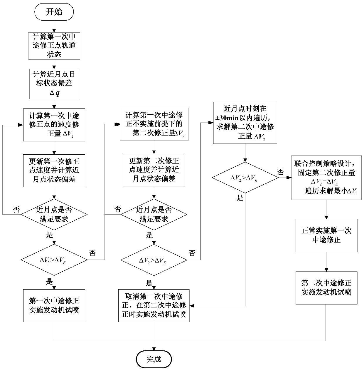
[0019] The present invention will be described in detail below with reference to the drawings and embodiments.
[0020] The invention provides a test injection method for an orbital engine with a ground-moon transfer, which considers the implementation of the engine test injection during the midway correction of the ground-moon transfer. The midway correction of the Earth-Moon transfer is used to correct the orbital deviation caused by errors such as carrier entry and orbit determination, so as to ensure that the probe can reach the moon in the expected near-moon state. Generally, 3 midway corrections are arranged for the lunar transfer segment. In actual flight, 1-2 midway corrections will be cancelled according to the orbital parameters and control implementation. However, the amount of orbit change for midway correction is usually small, and it does not need to be implemented with a large thrust engine. Especially when the accuracy of carrier launch and orbit determination is high, the speed increase produced by the shortest time of the orbit control engine test injection often exceeds the midway correction required by the transfer orbit itself. Therefore, it is necessary to comprehensively consider the midway correction arrangement, and reasonably choose the timing and strategy of test spraying.
[0021] The present invention first calculates the first halfway correction amount according to the track state. If the engine test injection produces a speed increment less than or equal to the first halfway correction amount, the engine test injection is performed during the first halfway correction; otherwise, the calculation is not performed. The second half-way correction amount based on the first half-way correction is executed. If the speed increment of the motor test injection is less than or equal to the second half-way correction amount, the first half-way correction will not be executed. The engine test injection is performed during the midway correction; if the engine test injection speed increment is greater than the second halfway correction amount, the difference between the engine test injection speed increase and the second halfway correction amount is calculated, and the The difference is set as the reverse correction amount of the first halfway correction, the first halfway correction is executed, and the engine test injection is performed during the second halfway correction.
[0022] Specific, such as figure 1 As shown, the test spray method of the present invention includes the following steps:
[0023] (1) Obtain the initial orbit parameters of the detector, including the initial time state, the midway correction point time, the transfer orbit end time, and the speed increment ΔV corresponding to the minimum startup time of the engine test injection E;
[0024] (2) Predict the position and velocity at the initial time in step (1) to the first midway correction point and the transfer orbit terminal time respectively, and obtain the deviation between the target state at the near-moon point and the predetermined amount;
[0025] (3) Calculate the first halfway correction based on the target state deviation of the transfer track terminal;
[0026] (4) Update the speed of the first midway correction point and forecast the time to the end of the transfer orbit. If the target state meets the requirements, obtain the first midway correction amount ΔV 1; If not satisfied, return to step (3);
[0027] (5) If ΔV 1 ΔV E , The engine test injection will be implemented during the first halfway correction, if ΔV 1 E , Forecast the position and velocity at the initial time in step (1) to the second midway correction time;
[0028] (6) Based on the obtained deviation of the terminal target state, the second half-way correction is calculated without implementing the first half-way correction;
[0029] (7) Update the speed of the second halfway correction point and forecast the time to the end of the transfer track. If the requirements are met, the second halfway correction amount ΔV will be obtained without implementing the first halfway correction 2; If not satisfied, return to step (6);
[0030] (8) If ΔV 2 ΔV E , The first halfway correction will not be implemented, and the engine test injection will be implemented during the second halfway correction. If ΔV 2 E , Go to step (9);
[0031] (9) Adjust the terminal time of the transfer track until the second halfway correction ΔV 2 =ΔV E; If ΔV 2 Always less than ΔV E , Go to step (10);
[0032] (10) Adopt the joint control strategy of the first and second midway corrections, and fix the size of the second correction as ΔV E , According to steps (2)-(4), adjust the velocity component of the first correction to aim at the near-moon point t f The target state; select the altitude angle and azimuth angle of the second midway correction as the optimization variables, until the first midway correction with the optimal speed increment is obtained.
[0033] This paper combines the engine test injection demand with the midway correction strategy of the ground-moon transfer to ensure that the engine test injection can be implemented with the optimal strategy for midway correction speed increment under different error conditions.
[0034] A specific example is given below for illustration:
[0035] (1) Obtain the initial orbital parameters of the detector, including the initial time t 0 Position velocity (r 0 ,v 0 ), the first and second halfway correction point time t 1 And t 2 , Transfer track terminal time t f , The speed increment ΔV corresponding to the minimum startup time of the engine test injection E;
[0036] (2) Change the position and velocity of the initial moment in step (1) (r 0 ,v 0 ) Respectively forecast to t 1 And transfer track terminal time t f. According to the position velocity of the terminal moment (r f ,v f ) To solve the terminal target state.
[0037] The target variable of the earth-moon transfer terminal required by the project is generally the height of the near-moon point H m , The inclination of the near moon point and the position vector and velocity vector of the detector relative to the center of the moon are perpendicular (ie the near moon point), and the terminal state is represented by q:
[0038]
[0039]
[0040] By q 2 And q 3 The expression of: q 2 Represents the cosine of the angle between the speed of the probe relative to the moon and the radius of the moon center at the near moon point, q 3 Indicates the instantaneous orbital inclination of the probe relative to the equatorial plane of the moon at the near-moon point.
[0041] Solve the terminal target state and the predetermined state q * Deviation
[0042] Δq=q-q *
[0043] (3) The velocity vector of the detector at the first midway correction is recorded as
[0044]
[0045] The relationship with the target state of the terminal can be described as q=f(v 1 ), the first halfway correction speed increment can be calculated according to the terminal target state deviation
[0046]
[0047] (4) Update the speed of the first halfway correction point to v 1 =v 1 +Δv 1 , And forecast the time to the end of the transfer orbit. If the requirements are met, the first midway correction speed increment Δv will be obtained 1; If not satisfied, return to step (3) to continue iterating to meet the target requirements;
[0048] (5) For the Δv obtained in step (4) 1 Modulo
[0049] ΔV 1 =|Δv 1 |
[0050] If ΔV 1 ≥ΔV E , The engine test injection will be implemented during the first halfway correction, if ΔV 1 E , Predict the position and velocity at the initial moment in step (1) to t 2 , Get the velocity vector at the second halfway correction
[0051]
[0052] (6) With reference to the method in step (3), the relationship between the speed vector at the second halfway correction and the terminal target state is recorded as q=g(v 2 ), the second halfway correction speed increment can be calculated based on the deviation of the terminal target state obtained without implementing the first halfway correction
[0053]
[0054] (7) Update the speed of the second halfway correction point to v 2 =v 2 +Δv 2 , And forecast to the end of the transfer track. If the requirements are met, the second halfway correction speed increment Δv without the first halfway correction is obtained 2; If not satisfied, return to step (6);
[0055] (8) For the Δv obtained in step (7) 2 Modulo
[0056] ΔV 2 =|Δv 2 |
[0057] If ΔV 2 ≥ΔV E , Cancel the first halfway correction, and implement engine test injection during the second halfway correction. If ΔV 2 E , Go to step (9);
[0058] (9) in (t f -30min, t f +30min] to traverse the transfer track terminal time, and refer to steps (6)(7) to calculate the second halfway correction until the second halfway correction ΔV 2 =ΔV E; If the traversal is completed, ΔV 2 Always less than ΔV E , Go to step (10);
[0059] (10) Adopt the joint control strategy of the first and second halfway corrections, and fix the size of the second halfway correction as ΔV E , Referring to steps (2) ~ (4), adjust the velocity component of the first correction to aim at the near moon point t f The target state, solve for Δv 1; Select the altitude angle α for the second midway correction 2 And azimuth β 2 As an optimization variable, the height angle α 2 , Azimuth β 2 And Δv 2 The conversion relationship between is as follows
[0060] ΔV 2 =|Δv 2 | Δv 2x =ΔV 2 sinα 2 sinβ 2
[0061] α 2 =cos -1 (ΔV 2z /|Δv 2 |), Δv 2y =ΔV 2 sinα 2 cosβ 2
[0062] β 2 =tan -1 (Δv 2y /Δv 2x ) Δv 2z =ΔV 2 cosα 2
[0063] The height angle α 2 In the range of [-90°, 90°], the azimuth angle β 2 Traverse in [0°,360°], and solve the altitude angle α that makes the total speed increment optimal for two halfway corrections 2 And azimuth β 2.
[0064] It should be noted that the content that is not described in detail in the specification of the present invention belongs to the well-known technology of those skilled in the art.
[0065] In summary, the above are only preferred embodiments of the present invention, and are not used to limit the protection scope of the present invention. Any modification, equivalent replacement, improvement, etc., made within the spirit and principle of the present invention shall be included in the protection scope of the present invention.

PUM

no PUM

Description & Claims & Application Information

We can also present the details of the Description, Claims and Application information to help users get a comprehensive understanding of the technical details of the patent, such as background art, summary of invention, brief description of drawings, description of embodiments, and other original content. On the other hand, users can also determine the specific scope of protection of the technology through the list of claims; as well as understand the changes in the life cycle of the technology with the presentation of the patent timeline. Login to view more.
Why Eureka
Try Eureka