
A kind of logistics sorting and conveying equipment

A conveying equipment and logistics technology, applied in the field of logistics, can solve the problems of package deviation, affecting conveying speed, blocking, etc., to achieve the effect of increasing friction, preventing sliding deviation, and improving logistics conveying speed

Active Publication Date: 2021-06-15
临沂罗开投资有限公司
View PDF6 Cites 2 Cited by
  • Summary
  • Abstract
  • Description
  • Claims
  • Application Information

AI Technical Summary

Problems solved by technology

[0003] Since the outer surface of the cylindrical parcel is arc-shaped, and the conveying roller of the conveying equipment is also cylindrical, when the parcel is conveyed longitudinally, the arc-shaped surface of the parcel is in line contact with the arc-shaped surface of the conveying roller, resulting in Sliding occurs during the conveying process, which causes the package to shift on the conveying roller, and then touches the side wall obliquely, making it blocked during the conveying process and affecting the conveying speed

Method used


Image

  • A kind of logistics sorting and conveying equipment
  • A kind of logistics sorting and conveying equipment
  • A kind of logistics sorting and conveying equipment

Examples


Embodiment 1

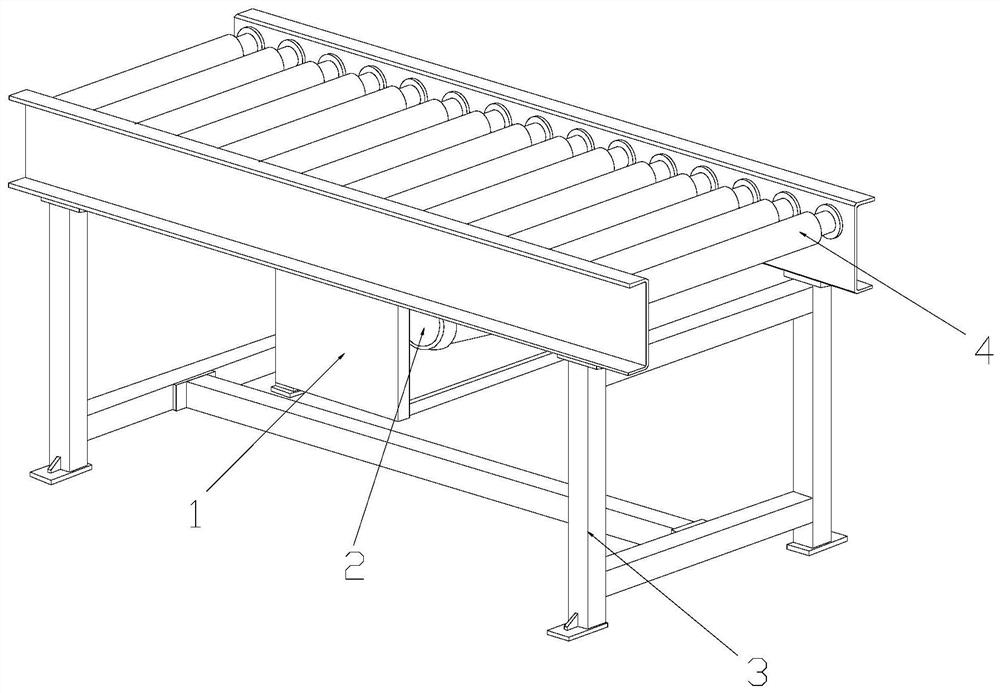
[0028] Example 1: Please refer to Figure 1-Figure 4 , the specific embodiments of the present invention are as follows:

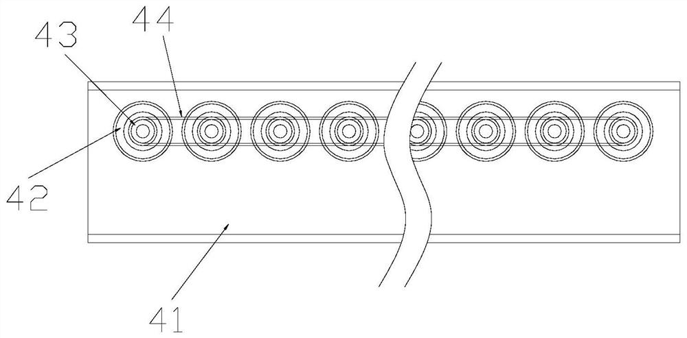
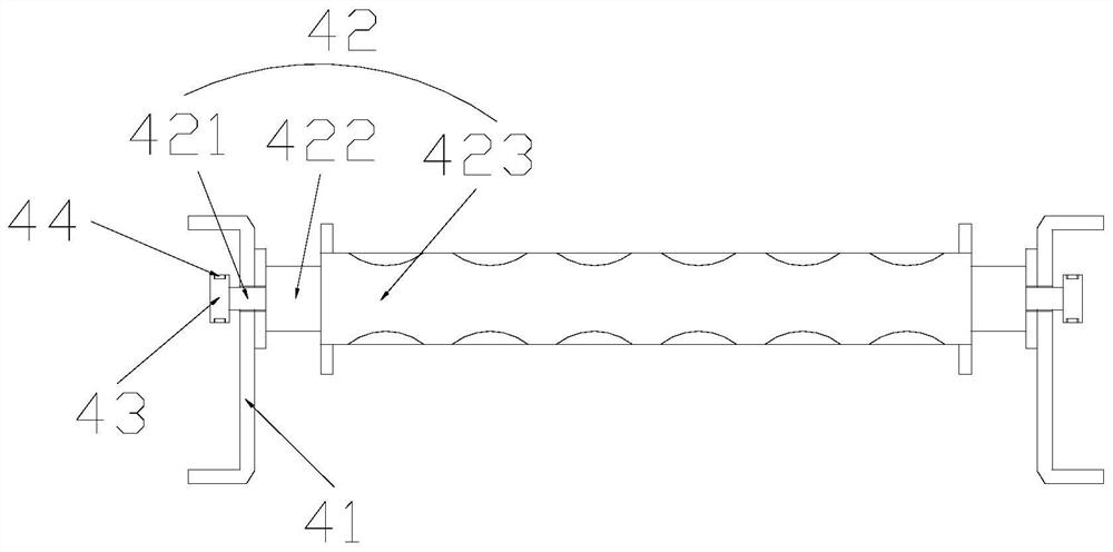
[0029] Its structure includes a chassis 1, a motor 2, a frame 3, and a conveying structure 4. The motor 2 is horizontally installed inside the chassis 1 and fixed with bolts. The frame 3 is fixed on the lower end of the conveying structure 4 and welded together. The chassis 1 is horizontally installed on the inner upper end of the frame 3, and the motor 2 is mechanically connected to the conveying structure 4 through a chain; the conveying structure 4 includes side plates 41, conveying rollers 42, pulleys 43, and belts 44 Horizontally installed between the side plates 41 and connected by hinges, the pulley 43 is installed on the side of the conveying roller 42 and engaged with each other, and the pulleys 43 are connected by a belt 44 .

[0030] refer to image 3 The conveying roller 42 includes a rotating shaft 421, a connecting shaft 422, and an adaptin...

Embodiment 2

[0035] Example 2: Please refer to Figure 4-Figure 7 , the specific embodiments of the present invention are as follows:

[0036] The adaptive roller 423 includes a protective plate 23a, a roller body 23b, a bump 23c, and a groove 23d. The protective plate 23a is installed on both sides of the roller body 23b and welded together, and the bump 23c is annularly installed outside the roller body 23b. surface, and is located between the grooves 23d, the grooves 23d are embedded in the inner side of the roller body 23b and are an integral structure, and the protrusions 23c protrude from the outer surface of the roller body 23b, and slowly move from a high place to both sides. The slowing down slope is on the same arc surface as the groove 23d.

[0037] refer to Figure 4 , Image 6 , the inner side of the groove 23d is provided with a movable structure d1, the movable structure d1 is provided with multiple and evenly distributed in the inner side of the groove 23d, the movable s...


PUM


Abstract

The invention discloses a logistics sorting and conveying equipment. Its structure includes a case, a motor, a frame and a conveying structure. The motor is installed horizontally inside the case, the frame is fixed at the lower end of the conveying structure, the case is horizontally installed at the upper end of the inner side of the frame, and the motor is installed horizontally at the inner side of the case. It is mechanically connected with the conveying structure through a chain. The conveying structure includes side plates, conveying rollers, pulleys, and belts. The conveying rollers are horizontally installed between the side plates and are connected by hinges. The belt pulleys are installed on the side of the conveying rollers. In the present invention, a conveying roller is set between the side plates, which limits the position of the package, prevents the sliding offset during the conveying process, and better conveys the cylindrical package; a movable structure is arranged inside the groove, It makes close contact with the cylindrical package, and increases the friction between them, while preventing it from sliding and offsetting, it can better convey it and improve the logistics conveying speed.

Description

technical field [0001] The invention belongs to the field of logistics, and in particular relates to a logistics sorting and conveying equipment. Background technique [0002] With the current rapid development of the Internet, more and more people are shopping on the Internet, and more products need to be delivered by logistics, which greatly stimulates the logistics industry. With more and more packages in the logistics industry, there will be These logistics parcels need to be sorted and transported, and then logistics sorting and conveying equipment is needed to perform fast sorting and transport and speed up the delivery efficiency of logistics. There are various logistics parcels, including cylindrical parcels , all need to be sorted and transported, but the existing technology has the following deficiencies: [0003] Since the outer surface of the cylindrical parcel is arc-shaped, and the conveying roller of the conveying equipment is also cylindrical, when the parce...

Claims


Application Information

Patent Timeline
Patent Type & Authority Patents(China)
IPC IPC(8): B65G13/07B65G39/02
CPCB65G13/07B65G39/02
Inventor 冯丽静李传威刘兆喜
Owner 临沂罗开投资有限公司
Learn More