A textile equipment with cleaning function

A textile equipment and functional technology, applied in the field of textile equipment with cleaning function, can solve problems such as unusable, easy to break, yarn guide frame, etc., and achieve the effect of easy removal and improved cleaning effect

Active Publication Date: 2022-05-10
宁国金诺制衣有限公司
View PDF15 Cites 0 Cited by
  • Summary
  • Abstract
  • Description
  • Claims
  • Application Information

AI Technical Summary

Problems solved by technology

[0002] Textile equipment will produce a lot of lint during operation, especially in spinning equipment, lint is often stuck on the yarn guide frame, causing the yarn guide frame to be unusable, and the yarn is easy to break when the yarn is spun and wound. Phenomenon

Method used


Image

  • A textile equipment with cleaning function
  • A textile equipment with cleaning function
  • A textile equipment with cleaning function

Examples


Embodiment 1

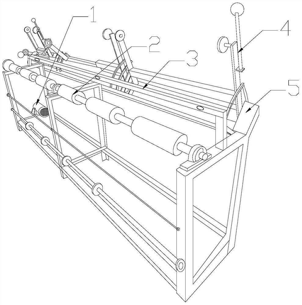
[0027] see Figure 1-Figure 6 , a kind of textile equipment with cleaning function, the present invention provides a kind of textile equipment with cleaning function, its structure includes motor 1, winding hammer 2, yarn guide cleaning frame 3, thread guide 4, support 5, and described support 5 The bottom of the motor is provided with a motor 1, the motor 1 is mechanically connected to the winding hammer 2, the winding hammer 2 is installed on the front part of the top of the bracket 5, the winding hammer 2 and the wire guide 4 are opposite, and the wire The device 4 is vertically fixed on the support 5, and the yarn guide cleaning frame 3 is located between the winding hammer 2 and the thread guide 4.

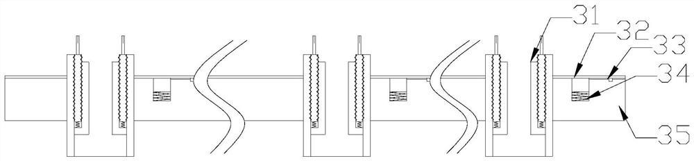
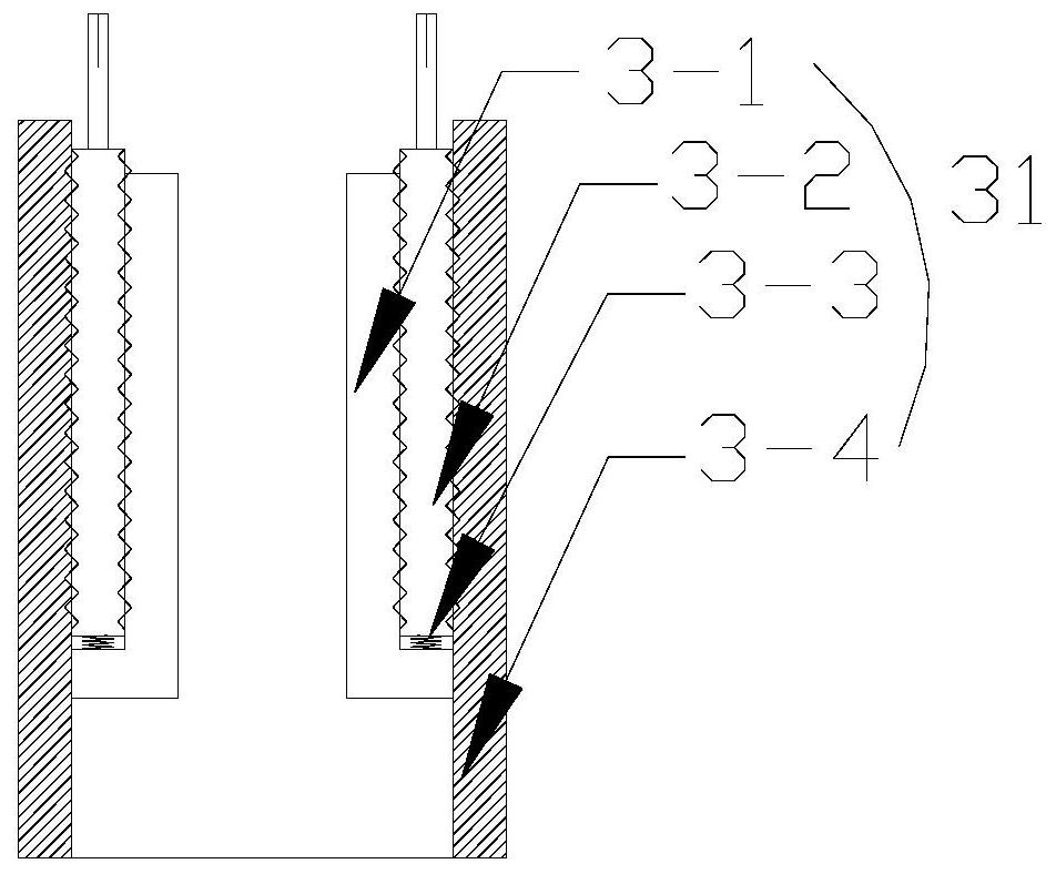
[0028] The yarn guide cleaning frame 3 is provided with a staggered tube 31, a vibrating plate 32, a connecting buckle 33, a spring 34, and a main board 35. The main board 35 is provided with more than two staggered tubes 31, and the two staggered tubes 31 Evenly and equidis...

Embodiment 2

[0034] see Figure 1-Figure 6 , a kind of textile equipment with cleaning function, the present invention provides a kind of textile equipment with cleaning function, its structure includes motor 1, winding hammer 2, yarn guide cleaning frame 3, thread guide 4, support 5, and described support 5 The bottom of the motor is provided with a motor 1, the motor 1 is mechanically connected to the winding hammer 2, the winding hammer 2 is installed on the front part of the top of the bracket 5, the winding hammer 2 and the wire guide 4 are opposite, and the wire The device 4 is vertically fixed on the support 5, and the yarn guide cleaning frame 3 is located between the winding hammer 2 and the thread guide 4.

[0035]The yarn guide cleaning frame 3 is provided with a staggered tube 31, a vibrating plate 32, a connecting buckle 33, a spring 34, and a main board 35. The main board 35 is provided with more than two staggered tubes 31, and the two staggered tubes 31 Evenly and equidist...


PUM


Abstract

The invention discloses a textile device with a cleaning function. The structure includes a motor, a winding hammer, a yarn guide cleaning frame, a wire guide, and a bracket. The wire hammer is installed on the front part of the top of the bracket, the wire winding hammer and the wire guide are opposite to each other, the wire guide is vertically fixed on the bracket, and the yarn guide cleaning frame is located between the wire winding hammer and the wire guide, and the present invention utilizes the intermediate moving cylinder to first compress inwards , and then because of the inertia of the second spring springing outwards, the lint adhering to the outside of the scatter tube is removed, further improving the removal effect of lint, and the length of the moving tube is longer than the length of the inner tube, so as to avoid mutual contact between the two. The moving cylinder cannot be removed or attached.

Description

technical field [0001] The invention relates to the field of textile equipment, in particular to a textile equipment with a cleaning function. Background technique [0002] Textile equipment will produce a lot of lint during operation, especially in spinning equipment, lint is often stuck on the yarn guide frame, causing the yarn guide frame to be unusable, and the yarn is easy to break when the yarn is spun and wound. Phenomenon. Contents of the invention [0003] Aiming at the deficiencies of the prior art, the present invention is achieved through the following technical solutions: a textile device with a cleaning function, the structure of which includes a motor, a winding hammer, a yarn guide cleaning rack, a thread guide, and a bracket, and the bracket’s There is a motor at the bottom, the motor is mechanically connected with the winding hammer, the winding hammer is installed at the front of the top of the bracket, the winding hammer is opposite to the lead guide, ...

Claims


Application Information

Patent Timeline
Patent Type & Authority Patents(China)
IPC IPC(8): D01H11/00
CPCD01H11/00
Inventor 陈飞
Owner 宁国金诺制衣有限公司
Why Eureka
Try Eureka