Positioning buffer structure of driver's door of bus

A technology of buffer structure and driver's door, applied in the direction of vehicle parts, door/window accessories, building structure, etc., can solve the problem of buffer force and positioning not helpful, increase the weight of door frame or the complexity of structure, and not meet the light weight of vehicles requirements and other issues, to achieve the effect of flexible and convenient opening and closing of the driver's door, eliminating impact and noise

Pending Publication Date: 2020-07-03
湖南晟成汽车零部件有限公司
View PDF2 Cites 2 Cited by
  • Summary
  • Abstract
  • Description
  • Claims
  • Application Information

AI Technical Summary

Problems solved by technology

But this utility model can only provide pressure only by the elasticity of the rubber, and cannot provide the holding force to the door. According to its instruction manual, this utility model relies on the magnetism of the buffer strip to provide the inward holding force between the door and the door frame. This requires the door frame to be made of ferromagnetic material or to be inlaid with ferromagnetic material, and the material of the existing bus driver's door and the door frame is aluminum alloy, which will increase the weight of the door frame or the complexity of the structure, which does not meet the requirements. Lightweight requirements of vehicles; in addition, as shown in the accompanying drawings, the utility model buffer strip is arranged in a closed rectangular ring to abut against the surface of the cabinet body, and the function of the side protrusions around it is only to increase the firmness of the assembly of the buffer strip. Cushioning and positioning don't help

Method used


Image

  • Positioning buffer structure of driver's door of bus
  • Positioning buffer structure of driver's door of bus
  • Positioning buffer structure of driver's door of bus

Examples


Embodiment Construction

[0027] Specific embodiments of the present invention are provided below in conjunction with the accompanying drawings.

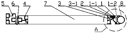
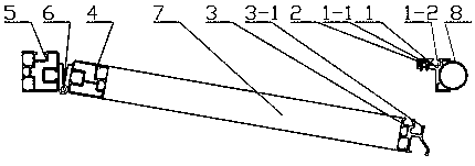
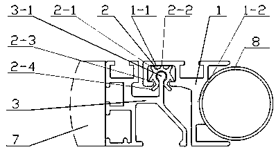
[0028] Such as Figure 1 ~ Figure 4 As shown, the technical solution adopted in the present invention comprises a first door frame column 1, a first door column 3, a second door frame column 5 and a second door column 4, and the second door frame column 5 is installed on the vehicle body floor during use, so The second door column 4 is hinged on the second door frame column 5 through a hinge 6; the second door column 4 and the first door column 3 are connected together by a beam 7 to form a frame structure of the driver's door; When the first door frame column 1 is in use, it is installed on the vehicle body floor, a C-shaped groove 1-1 with a lower end opening is provided on the left side of the first door frame column 1, and a user is provided on the right side of the first door frame column 1. In the concave arc 1-2 matched with the installation column 8...


PUM


Abstract

A positioning buffer structure of a driver's door of a bus belongs to the technical field of buses and overcomes the problems in the prior art that the operating force of closing the driver door is increased in order to reduce noise, which affects the operation flexibility of the driver door, and that the existing buffer block can only provide outward pressure and cannot provide inward pulling force, which is not suitable for positioning buffer of the driver's door of the bus, wherein the left side of a first door frame column is provided with a C-shaped groove with an open end at the left, the C-shaped groove is installed with a positioning buffer bar, the main body of the cross section of the positioning buffer bar is a C-shaped open ring with a lower end opening, a first protrusion, a second protrusion, a third protrusion and fourth third protrusion are provided on the outer circumference of the C-shaped open ring of the positioning buffer bar, and the first door column is providedwith a round head protrusion matching the inner circle of the C-shaped open ring. The invention has the beneficial effect of not only improving the suppression of vibration shock between a lock tongueand a lock hole and reducing noise, but also not increasing the operating force of closing the driver's door, and not affecting the operation flexibility of the driver's door.

Description

technical field [0001] The invention belongs to the field of bus technology, in particular to a bus driver's door positioning buffer structure. Background technique [0002] Since the driver is violated and interfered by other passengers during the operation of the bus, it may lead to serious accidents. , Some buses have installed isolation guards in the bus driving area, and the isolation guards include fixed enclosure partitions and driver's doors for drivers to enter and exit. In terms of the driver's door, some existing technologies use hinges to hinge the driver's door on the surrounding partition. The driver's door with this hinged structure is equipped with a lock that controls the opening and closing of the driver's door. There is a lock body with a retractable lock tongue and a lock hole installed on the surrounding partition. When the driver's door is closed, the lock tongue extends into the lock hole to prevent the driver's door from being opened. When the driver...

Claims


Application Information

Patent Timeline
Patent Type & Authority Applications(China)
IPC IPC(8): E05F5/06E05B17/00B60R21/12
CPCB60R21/12E05B17/0041E05F5/06E05Y2900/506E05Y2900/531
Inventor 唐少华
Owner 湖南晟成汽车零部件有限公司
Why Eureka
Try Eureka