Magnetic levitation camera rotation control structure and rotatable magnetic levitation camera
A control structure and magnetic levitation technology, which is applied in the direction of closed-circuit television systems, supporting machines, mechanical equipment, etc., can solve the problems of complex control methods and difficult implementation, and achieve the effects of simplifying control methods, reducing production costs and use costs
- Summary
- Abstract
- Description
- Claims
- Application Information
AI Technical Summary
Problems solved by technology
Method used
Image

Examples
Embodiment 1
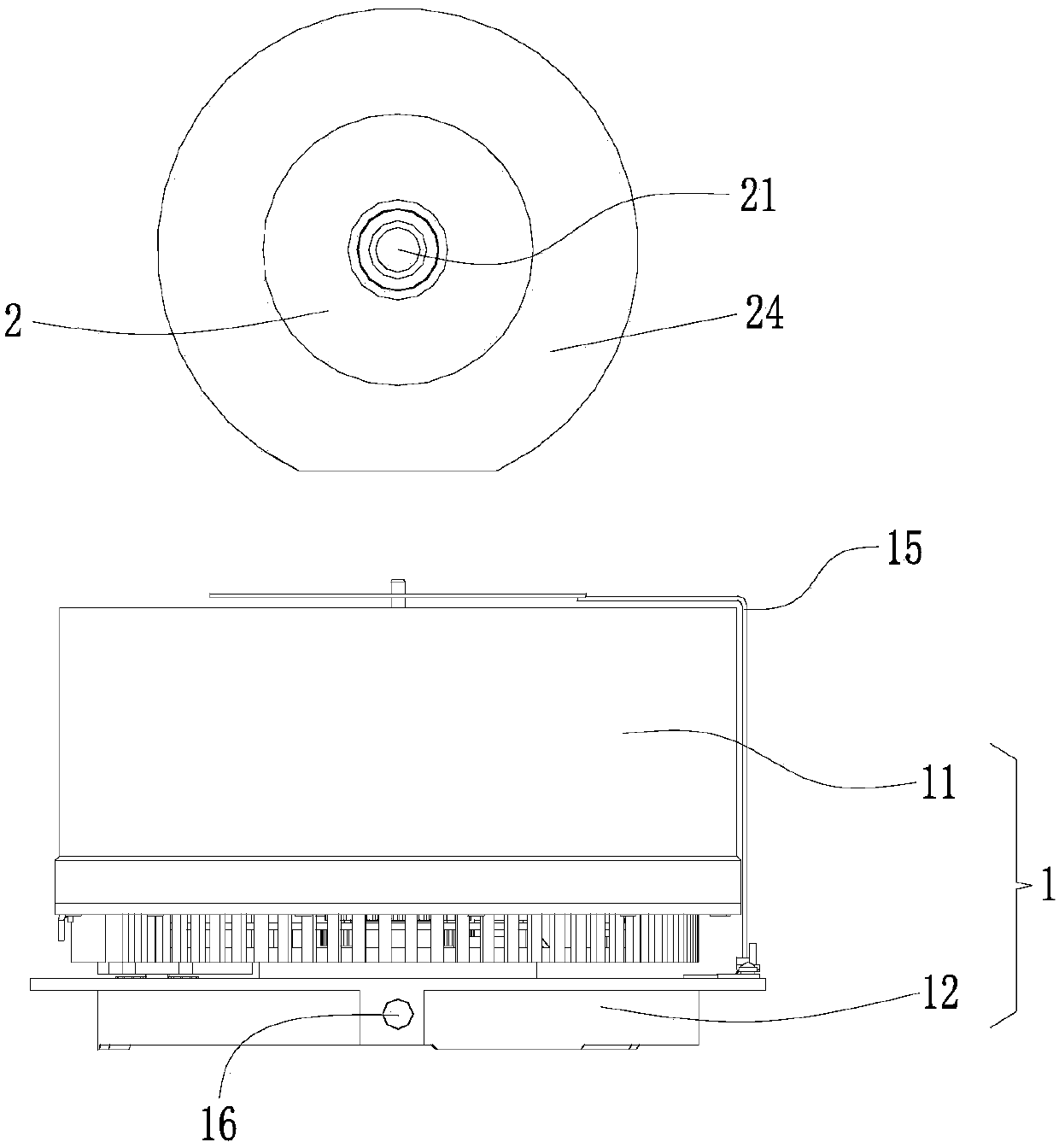
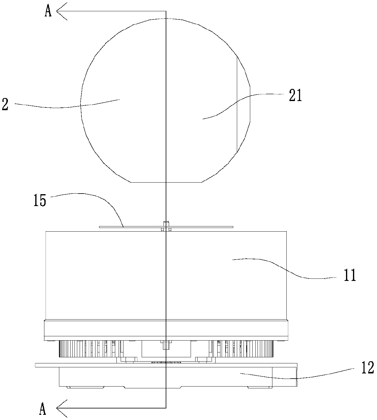
[0026] see Figure 1 to Figure 3 , figure 1 It is a schematic structural diagram of a rotatable magnetic levitation camera according to an embodiment of the present invention.
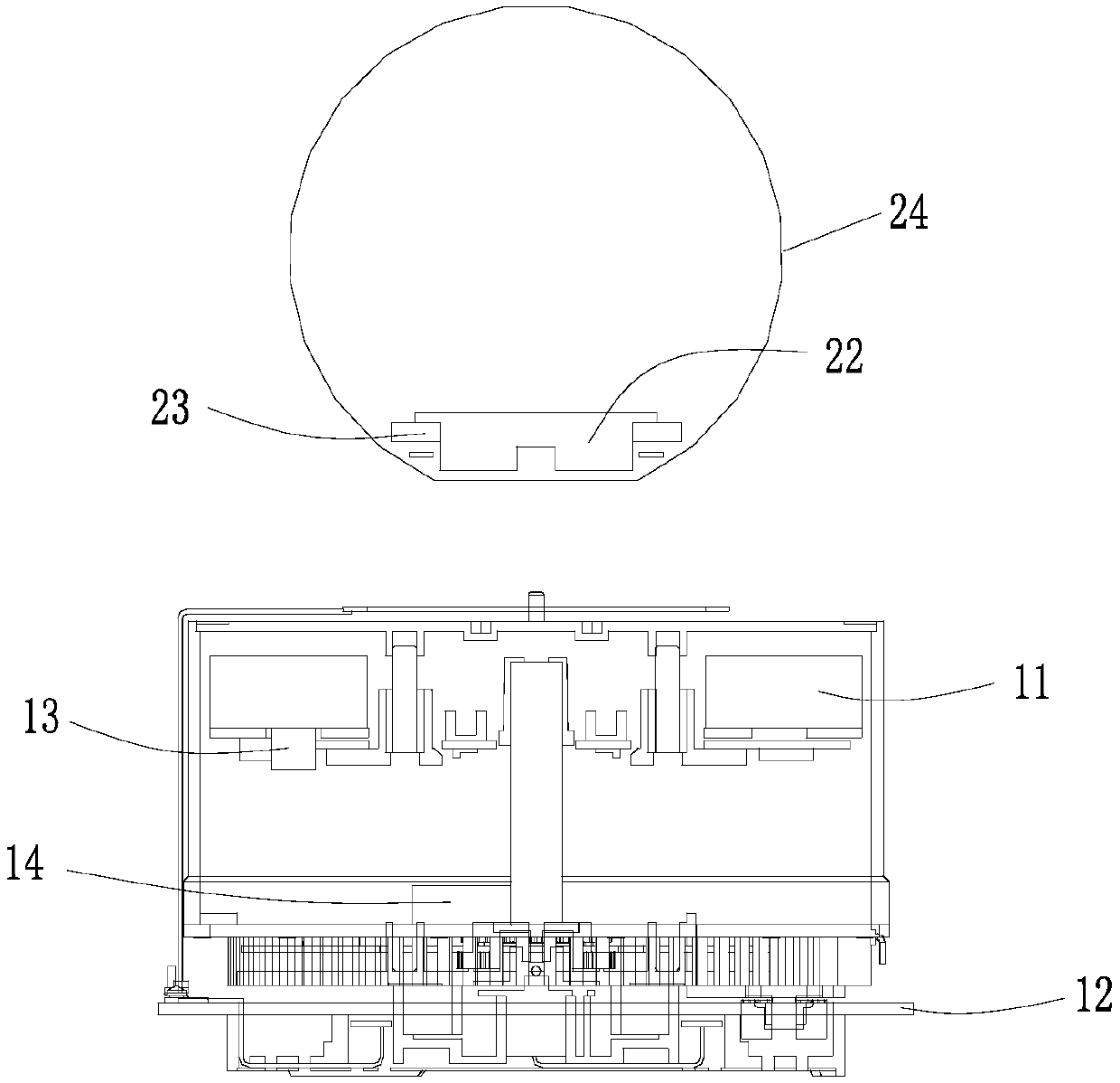
[0027] Such as figure 1 As shown, a rotatable magnetic levitation camera includes: a magnetic levitation base 1 and a magnetic levitation camera 2 . Wherein, the magnetic levitation base 1 comprises a magnetic levitation magnetic seat 11 and a chassis 12, the magnetic levitation magnetic seat 11 is arranged on the chassis 12 and is rotatable relative to the chassis 12, and the magnetic levitation magnetic seat 11 is provided with at least four first magnetic Positioning block 13, described chassis 12 is also provided with and is used to drive the rotating drive part 14 of described magnetic levitation magnetic seat 11 rotation; Described magnetic levitation camera head 2 comprises camera main body 21, is arranged on the suspension magnet 22 of described camera main body 21 bottoms and setting At lea...
Embodiment 2
[0048] A rotatable maglev camera includes the above-mentioned maglev camera rotation control structure.
[0049]During the use or working process of the rotatable maglev camera, the maglev camera rotation control structure is provided with a maglev base 1 and a maglev camera 2, wherein a maglev magnetic seat 11 and a chassis 12 are set in the maglev pedestal 1, and the maglev magnetic seat 11 is provided with the chassis 12 and is relatively rotatably connected with the chassis 12, the magnetic levitation magnetic base 11 is provided with a plurality of first magnetic positioning blocks 13, and the chassis 12 is also provided with a rotary drive member 14 for driving the magnetic levitation magnetic base 11 to rotate; the magnetic levitation camera 2 includes Camera main body 21, levitation magnet 22 and the second magnetic positioning block 23 that is arranged on the bottom of this levitation magnet 22, the polarity of the opposite side of levitation magnet 22 and magnetic lev...
PUM
 Abstract
Description
Claims
Application Information
 - R&D
- Intellectual Property
- Life Sciences
- Materials
- Tech Scout
- Unparalleled Data Quality
- Higher Quality Content
- 60% Fewer Hallucinations
Browse by: Latest US Patents, China's latest patents, Technical Efficacy Thesaurus, Application Domain, Technology Topic, Popular Technical Reports.
© 2025 PatSnap. All rights reserved.Legal|Privacy policy|Modern Slavery Act Transparency Statement|Sitemap|About US| Contact US: help@patsnap.com