Material drying method with function of dynamic matching of dried materials and drying regions

A dynamic matching and material technology, which is applied in the direction of dryers, dryers, dryers, etc. of static materials, can solve the problems of less heat, uneven drying degree, waste, etc., to reduce heat emission and avoid drying degree Inconsistent, fully utilized heat effects

Inactive Publication Date: 2020-07-03
NANHUA UNIV
View PDF6 Cites 0 Cited by
  • Summary
  • Abstract
  • Description
  • Claims
  • Application Information

AI Technical Summary

Problems solved by technology

[0004] The purpose of the present invention is to overcome the deficiencies of the prior art, and provide a material drying method in which the drying material and the drying area are dynamically matched, which solves the problem that the existing drying equipment is prone to uneven drying degree, drying The problem of serious waste of heat when the amount of material is small

Method used


Image

  • Material drying method with function of dynamic matching of dried materials and drying regions
  • Material drying method with function of dynamic matching of dried materials and drying regions
  • Material drying method with function of dynamic matching of dried materials and drying regions

Examples


Embodiment 1

[0035] The material drying method in which the drying material is dynamically matched with the drying area is applied to a material drying device that can make full use of heat energy.

[0036] A material drying device that can make full use of heat energy, including a heating device and a drying chamber.

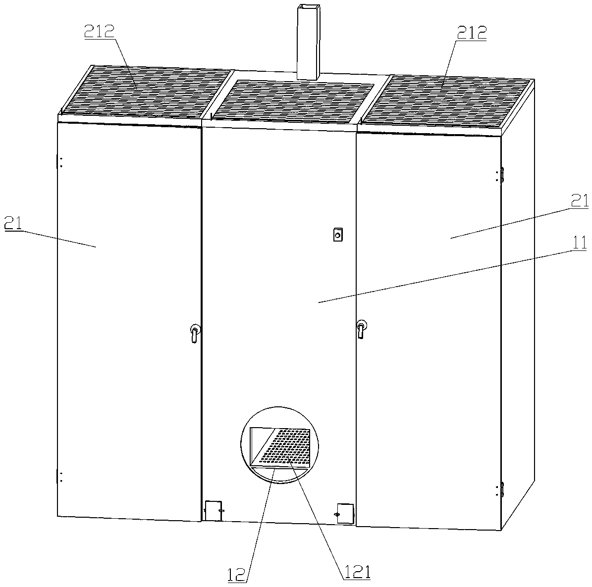
[0037] The heating device includes a housing A11 , a combustion chamber 12 , a flue 13 and an exhaust fan 14 . The housing A11 is provided with an inner cavity, the upper end of the housing A11 is provided with an air inlet A111, and the lower end of the housing A11 is provided with an air outlet A112. A combustion chamber is provided inside the combustion chamber 12 , and a fuel injection port 121 connected to the combustion chamber is provided outside the combustion chamber 12 .

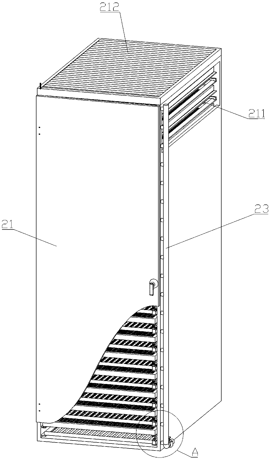
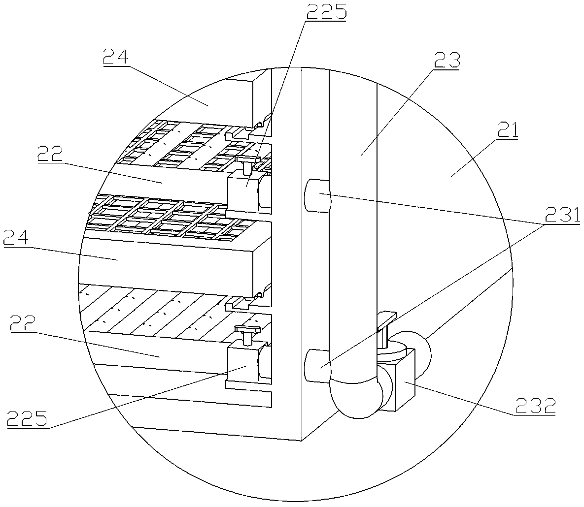
[0038] The drying chamber includes a housing B21 , a reticulated air pipe 22 , a main air pipe 23 and a shelf net 24 . The housing B is provided with an inner chamber, and the upper end of the...


PUM


Abstract

A material drying method with a function of dynamic matching of dried materials and drying regions is applied to a material drying device which can make full use of heat energy. The material drying method comprises the following steps that (1) the materials are laid; (2) the preparation work is conducted before drying operation is conducted, specifically, object placement mesh plates at the lowerends of bottommost-layer object placement mesh plates which are filled with the materials in a laid mode are taken down along insertion grooves, then separating plates which are matched with the insertion grooves are installed in the insertion grooves, and the regions, filled with the materials in a laid mode, of the interiors of drying chambers and vacant regions are separated by the separating plates; and (3) the materials are dried, specifically, after the materials are dried to a certain extent, louvers are adjusted, the opening degrees of vapor exhaust outlets are adjusted to be reduced,drying operation continues, the excessive heat is prevented from escaping from the vapor exhaust outlets, and finally the materials can meet the required drying degree. According to the material drying method, the areas of the drying regions are adjusted in the mode that the separating plates are installed in inner cavities of drying chamber shells B, the purpose that the hot air only exists in the drying regions is achieved in the mode that second-level valves on corresponding mesh-shaped air pipes are opened and closed, and dynamic matching of the quantity of the dried materials and the areas of the drying regions is achieved.

Description

technical field [0001] The invention relates to the technical field of material drying, in particular to a material drying method in which the drying material is dynamically matched with the drying area. Background technique [0002] There are various types of existing drying equipment. The structure of common drying equipment includes a drying chamber and a heating device located at the lower end of the drying chamber. Multi-layer mesh panels can be installed in the drying chamber to make full use of the internal space. The upper end of the chamber is provided with a steam exhaust hole for water vapor to be discharged. The materials to be dried are placed on the mesh plate in the drying chamber for drying. [0003] This existing drying equipment has the following deficiencies in actual use: 1. The heat distribution in the drying chamber is uneven. 2. When the thickness of the material to be baked is thick, the side of the material facing the heating device is prone to ove...

Claims


Application Information

Patent Timeline
IPC IPC(8): F26B9/10F26B21/02F26B25/18F23J15/06
CPCF23J15/06F26B9/10F26B21/002F26B21/004F26B21/02F26B25/18
Inventor 王伟李先飞王昌皓阙名星
Owner NANHUA UNIV
Why Eureka
Try Eureka