Light guide plate and backlight module

A light guide plate, a technology in the light guide plate, applied in the direction of light guides, optics, optical components, etc., can solve the problems of dot loss, film scratches, and size cannot be changed, and achieve the effect of preventing falling off and scratching the film

Active Publication Date: 2022-04-22
KUSN INFOVISION OPTOELECTRONICS
View PDF5 Cites 0 Cited by
  • Summary
  • Abstract
  • Description
  • Claims
  • Application Information

AI Technical Summary

Problems solved by technology

[0005] 1. The dots are generally set on the reflective surface of the light guide plate substrate by printing after the light guide plate substrate is formed. The position of the dots after printing is fixed and the size cannot be changed, so the LCM (LCD Module, LCD display module) cannot be changed. local brightness;
[0006] 2. The dots will fall off, and the dots that fall off will cause the diaphragm (a part of the display module) to be scratched

Method used


Image

  • Light guide plate and backlight module
  • Light guide plate and backlight module
  • Light guide plate and backlight module

Examples


Embodiment Construction

[0026] The specific implementation manners of the present invention will be further described in detail below in conjunction with the accompanying drawings and embodiments. The following examples are used to illustrate the present invention, but are not intended to limit the scope of the present invention.

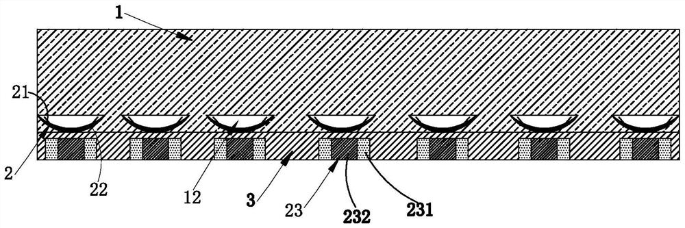
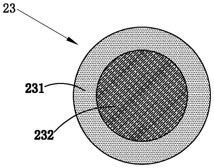
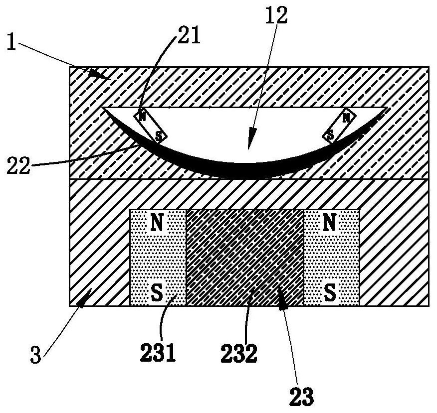
[0027] Such as figure 1 As shown, the light guide plate provided in this embodiment includes a light guide substrate 1, a fixed layer 3 is provided on one side of the light guide substrate 1, and a plurality of dots 2 are arranged in the light guide plate, and each dot 2 includes a reflective magnet 21, a carrying plate 22 and an electromagnet group 23, the carrying plate 22 is arranged in the light guide substrate 1, the reflective magnet 21 is movably arranged in the carrying plate 22, the electromagnet group 23 is arranged in the fixed layer 3, and the electromagnet group 23 is used to drive the light reflection The magnet 21 moves in the carrier plate 22 to change the...


PUM


Abstract

Light guide plate and backlight module. The present invention provides a light guide plate, including a light guide substrate, characterized in that a fixed layer is provided under the light guide substrate, and dots are distributed on the lower side of the light guide plate, and each dot includes a reflective magnet, a carrying plate and an electromagnet group, the carrying plate is arranged in the light guide substrate, the reflective magnet is movably arranged in the carrying plate, the electromagnet group is arranged in the fixed layer, the The electromagnet group is used to drive the reflective magnet to move in the carrying plate to change the size of each dot.

Description

technical field [0001] The invention relates to the field of electronic display equipment, in particular to a light guide plate and a backlight module. Background technique [0002] Liquid Crystal Display (LCD) is favored by users due to its small size, thin thickness, light weight and low power consumption. With the development of display technology, display devices such as mobile phones and computers have become more and more widely used. . [0003] The light guide plate is one of the important components of the liquid crystal display. Its working principle is: the light source enters the light guide plate from the side to generate countless total reflection light. Refracted light and scattered light destroy the reflection conditions and are emitted from the front of the light guide plate, so that the entire light guide plate panel emits uniform and high-brightness light. [0004] The network dots in the light guide plate of the prior art have the following defects: [...

Claims


Application Information

Patent Timeline
Patent Type & Authority Patents(China)
IPC IPC(8): G02B6/00G02F1/13357
CPCG02B6/0041G02B6/0055G02F1/133605
Inventor 崔佳明
Owner KUSN INFOVISION OPTOELECTRONICS
Why Eureka
Try Eureka