Die bonder

A die-bonding machine and die-bonding technology, applied in semiconductor/solid-state device manufacturing, electrical components, circuits, etc., can solve the problems of poor consistency of die-bonding quality and decline in die-bonding quality, reduce centrifugal force and ensure stability The effect of improving the efficiency of pick and place

Active Publication Date: 2020-07-03
SHENZHEN XINYICHANG TECH CO LTD
View PDF17 Cites 9 Cited by
  • Summary
  • Abstract
  • Description
  • Claims
  • Application Information

AI Technical Summary

Problems solved by technology

[0003] The purpose of the embodiments of the present application is to provide a die bonding machine to solve the problems in the related art that the die bonding efficiency will lead to a decrease in the die bonding quality and the poor consistency of the die bonding quality

Method used


Image

  • Die bonder
  • Die bonder
  • Die bonder

Examples


Embodiment Construction

[0055] In order to make the technical problems, technical solutions and beneficial effects to be solved by the present application clearer, the present application will be further described in detail below in conjunction with the accompanying drawings and embodiments. It should be understood that the specific embodiments described here are only used to explain the present application, and are not intended to limit the present application.

[0056] It should be noted that when an element is referred to as being “fixed on”, “disposed on” or “installed on” another element, it may be directly on the other element or indirectly on the other element. When an element is referred to as being "connected to" another element, it can be directly connected to the other element or indirectly connected to the other element.

[0057] In addition, the terms "first" and "second" are used for descriptive purposes only, and cannot be interpreted as indicating or implying relative importance or im...


PUM


Abstract

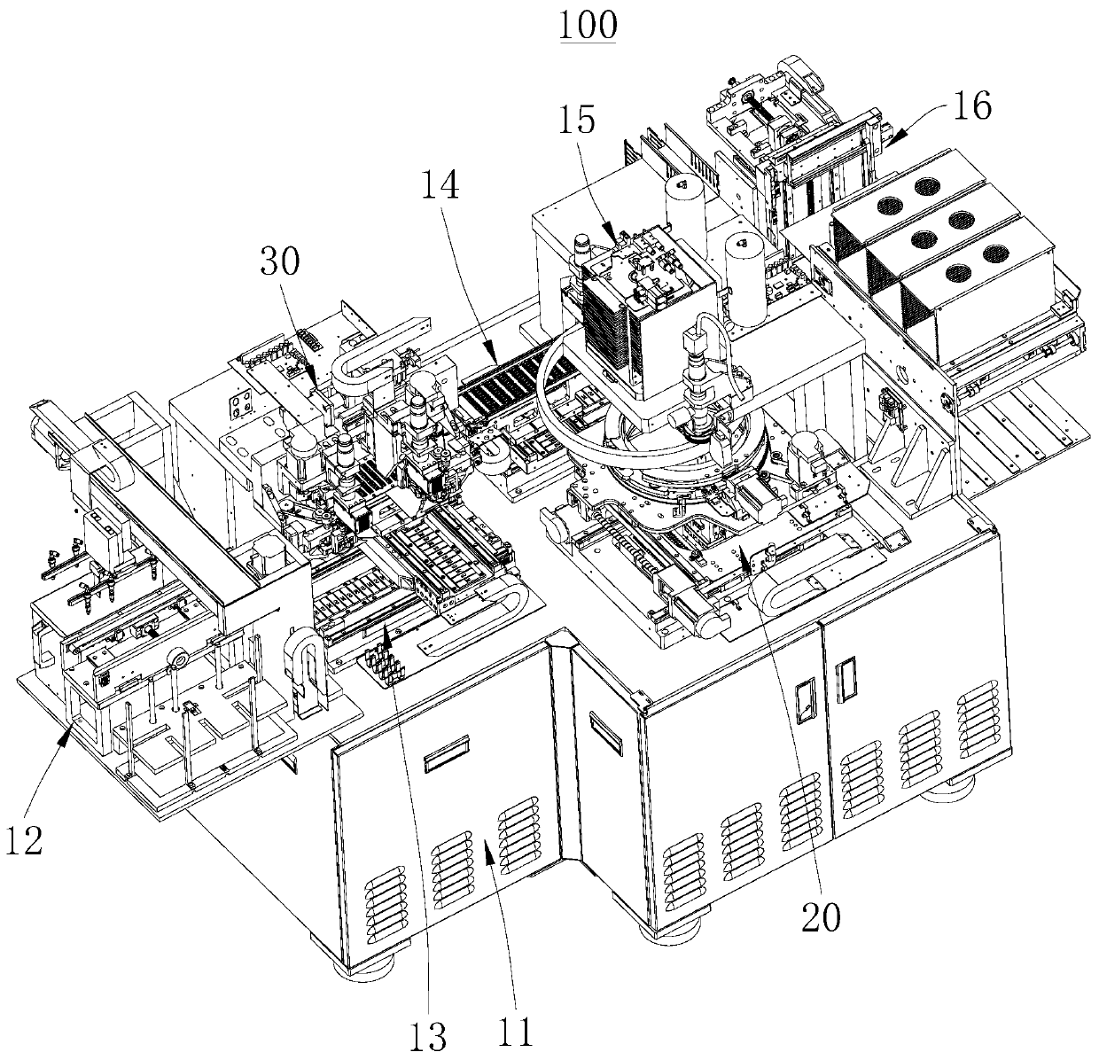
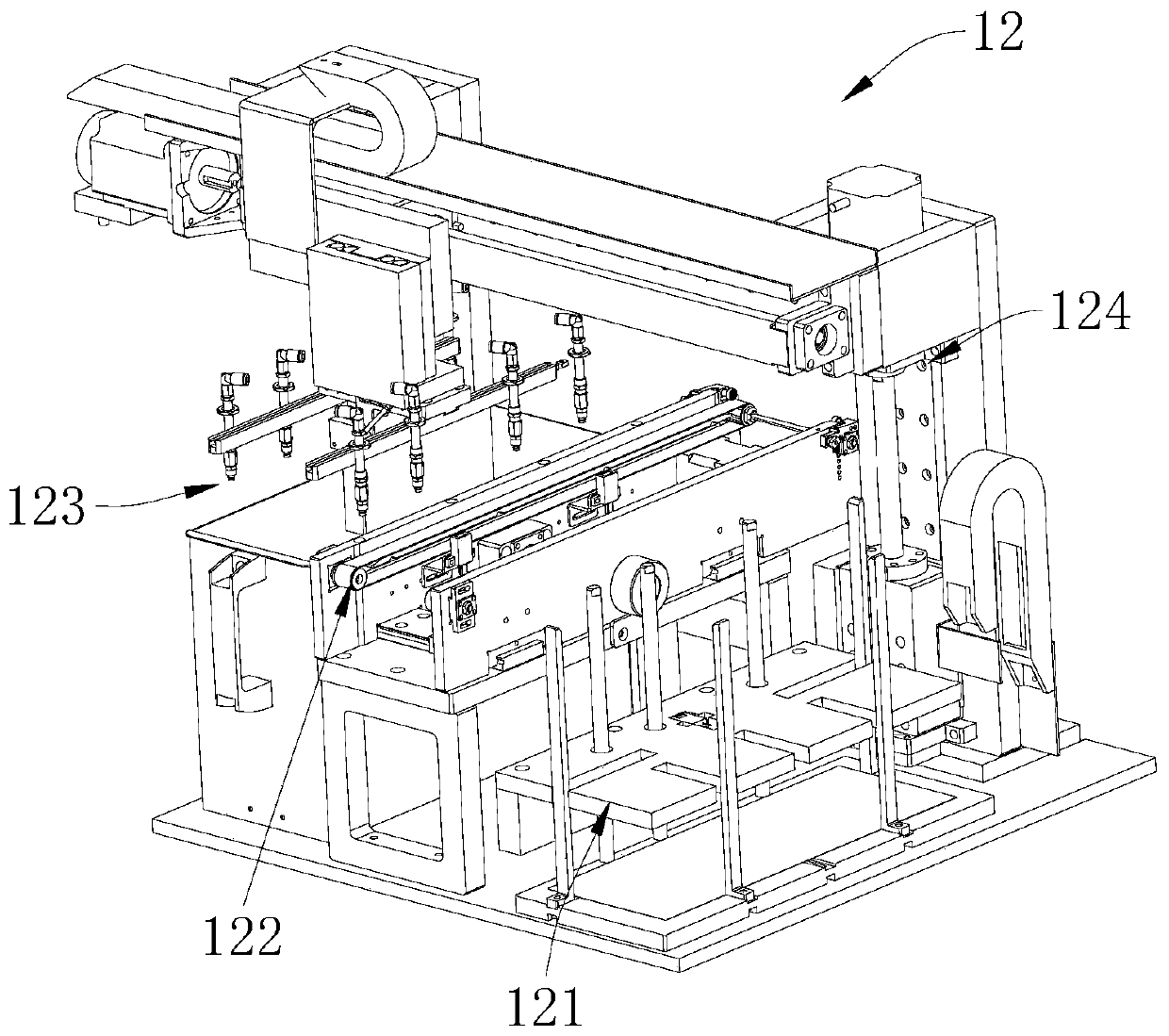
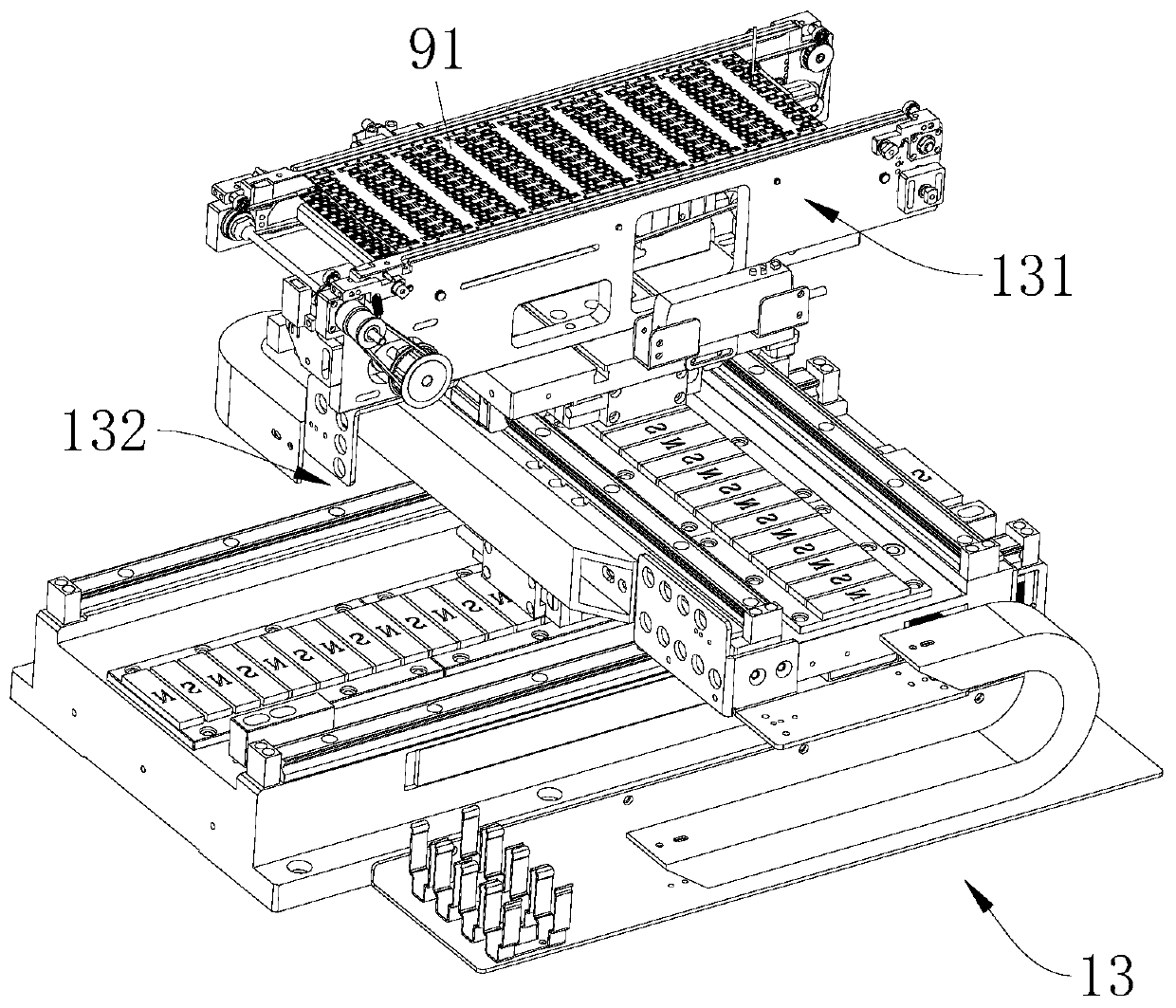
The invention provides a die bonder. The die bonder comprises a rack; a dispensing device; a dispensing shifting mechanism; a feeding mechanism; a die bonding swing arm device; a crystal supply platform; a die bonding displacement mechanism; and a material receiving mechanism. The die bonding swing arm device comprises a rotating frame, a plurality of die bonding swing arms, a lifter and a die bonding motor, and each die bonding swing arm is provided with a suction nozzle; the dispensing device comprises a plurality of dispensing modules. The invention provides a die bonder. According to the invention, the plurality of dispensing modules are combined with the plurality of die bonding swing arms, so that the operation speeds of the plurality of dispensing modules can be adjusted to be matched with the operation speeds of the plurality of die bonding swing arms on the premise of ensuring the dispensing precision and quality and ensuring the wafer taking and placing precision, the idle time of each dispensing module and each die bonding swing arm is reduced, and the die bonding efficiency is greatly improved.

Description

technical field [0001] This application belongs to the technical field of crystal bonding, and more specifically relates to a crystal bonding machine. Background technique [0002] Die bonding generally uses a glue dispenser to dispense glue on the position where the chip is installed on the bracket. Then move to the crystal bonding position, the crystal bonding swing arm picks up the wafer from the crystal supply platform, then rotates it and places it on the support to realize the crystal bonding. Since the crystal bonding swing arm needs to be aligned with the wafer on the crystal supply platform to suck the wafer, and then rotated to the crystal bonding position to place the wafer on the support during the crystal bonding, resulting in low bonding efficiency. The current way to improve the efficiency of die bonding is generally to set the operating speed of the dispensing device and the die bonding swing arm device to the highest set speed. However, the long-term opera...

Claims


Application Information

Patent Timeline
Patent Type & Authority Applications(China)
IPC IPC(8): H01L21/67H01L21/683
CPCH01L21/67092H01L21/6715H01L21/6838
Inventor 胡新荣
Owner SHENZHEN XINYICHANG TECH CO LTD
Why Eureka
Try Eureka