
A kind of automatic bonding equipment and assembly process of thermal battery current collector assembly

An automatic bonding and assembly process technology, applied in the direction of delayed action cells, etc., can solve the problems of low bonding precision, low assembly precision, and easy relative displacement, etc., to reduce the number of molds, improve installation accuracy, and improve production efficiency effect

Active Publication Date: 2017-03-29
CHINA THREE GORGES UNIV
View PDF3 Cites 0 Cited by
  • Summary
  • Abstract
  • Description
  • Claims
  • Application Information

AI Technical Summary

Problems solved by technology

[0003] The traditional assembly process mainly has the following defects: (1) Due to the relatively large error in the relative position of the asbestos ring and the stainless steel sheet assembled by hand, the assembly accuracy is not high, and the bonding assembly quality is low; method, the quality of glue application is poor, the efficiency is low, and it is easy to flow on the current collector in a large area, thereby affecting the performance of the thermal battery; (3) When using traditional asbestos ring cutting or punching methods to obtain asbestos rings of different sizes, it is necessary to use The processing process is complicated for different sizes of molds and tools; (4) When the asbestos rings are transported to the bonding platform, since the asbestos rings are thin, soft and of different sizes, the process of automatically holding, transporting and positioning the asbestos rings Complex and high cost; (5) The newly bonded asbestos ring and stainless steel current collector are prone to relative displacement during the handling process, which will result in low bonding accuracy

Method used


Image

  • A kind of automatic bonding equipment and assembly process of thermal battery current collector assembly
  • A kind of automatic bonding equipment and assembly process of thermal battery current collector assembly
  • A kind of automatic bonding equipment and assembly process of thermal battery current collector assembly

Examples


Embodiment Construction

[0028] Embodiments of the present invention will be further described below in conjunction with the accompanying drawings.

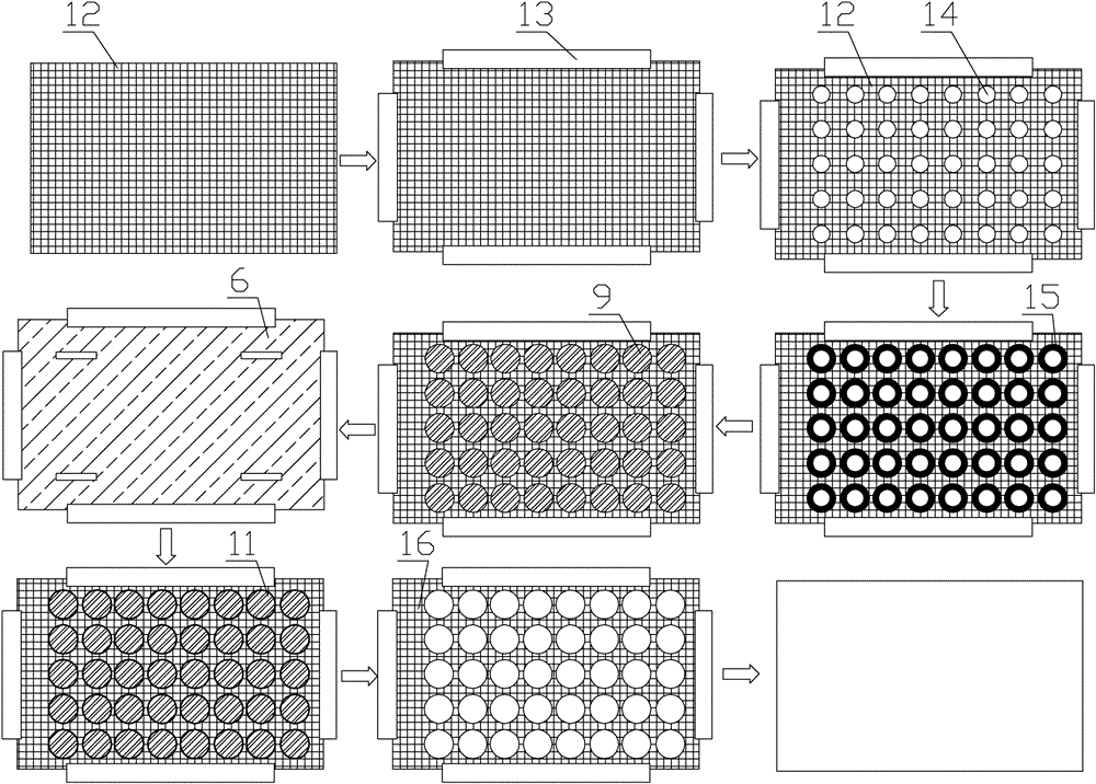
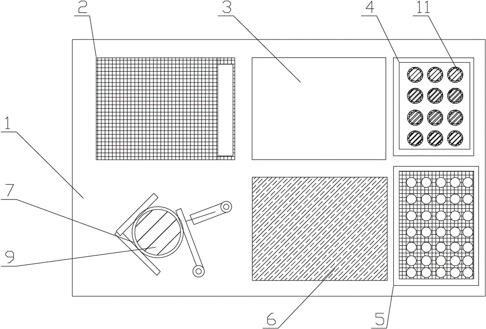
[0029] see figure 1 , is the flow chart of the assembly process of the current collector, which includes nine main steps: the first step, the asbestos paper 12 is automatically picked up and placed. Through the suction device installed on the two-dimensional numerical control platform 1, move to the placement area of ​​the high-temperature asbestos paper box 2 installed on the two-dimensional numerical control platform 1 to absorb the whole asbestos paper 12, and then place it on the two-dimensional numerical control platform 1. Combined with the working area 3, the preheating device of the high-temperature asbestos paper box 2 can preheat the asbestos paper 12, which is beneficial to the subsequent process; the suction device can use a manipulator to drive a vacuum suction cup to absorb the asbestos paper 12.

[0030] In the second step, the positionin...


PUM


Abstract

The invention relates to automatic bonding equipment for collector components of a thermal battery and an assembly process. The assembly process comprises nine main steps of automatically picking and placing asbestos paper; positioning and clamping the asbestos paper; cutting and removing an inner ring of the asbestos paper; dispensing the periphery of an inner circle area; placing stainless steel sheets; bonding and fixing the stainless steel sheets; cutting an outer circle of an asbestos ring; picking and placing collectors; and picking and placing leftover materials. Through designing the novel automatic bonding equipment for the collector components and changing the original assembly process to assemble the collectors, the installation accuracy of the inner circle areas of the stainless steel sheets and the collectors can be effectively improved, the dispensing quality is improved and the bonding quality is improved; the original stamping equipment is replaced by a numerical control laser cutting machine, so that the number of molds required by the stamping equipment is reduced, and the practicability of the equipment about the collectors of different sizes is improved; the collectors are assembled through matching of the equipment and the assembly process, so that the quality and the production efficiency of products are improved.

Description

technical field [0001] The invention relates to an automatic production equipment for a thermal battery, in particular to an automatic bonding equipment and an assembly process for a current collector assembly of a thermal battery. Background technique [0002] In the production process of thermal batteries, current collector components are needed to seal, discharge and collect current. Current collector components are assembled by bonding stainless steel sheets and asbestos rings with glue. The original assembly process is mainly The stainless steel sheets and asbestos rings of different sizes obtained by the punching machine and the cutting machine are bonded by manual glue spraying, and finally assembled into a collector sheet assembly. [0003] The traditional assembly process mainly has the following defects: (1) Due to the relatively large error in the relative position of the asbestos ring and the stainless steel sheet assembled by hand, the assembly accuracy is not h...

Claims


Application Information

Patent Timeline
Patent Type & Authority Patents(China)
IPC IPC(8): H01M6/36
CPCH01M6/36
Inventor 冯正华肖洒刘忠涛蔡资鉴蒲航肖隆恩
Owner CHINA THREE GORGES UNIV
Learn More