Light emitting device

A technology of light-emitting device and base plate, which is applied in the direction of electrical components, circuits, semiconductor devices, etc., can solve the problems of ineffective positioning of PCB boards, low setting height of LED lamp beads, and small application angle.

Inactive Publication Date: 2020-07-03
EVERLIGHT ELECTRONICS (CHINA) CO LTD
View PDF17 Cites 0 Cited by
  • Summary
  • Abstract
  • Description
  • Claims
  • Application Information

AI Technical Summary

Problems solved by technology

[0002] At present, the light-emitting device based on, for example, LED lamp beads as light-emitting parts, because the actual application angle of the existing LED lamp beads is relatively small, when the above-mentioned existing light-emitting devices are directly plugged into the PCB board, the setting height of the LED lamp beads is relatively low, so that Unable to meet the new demand for light-emitting devices in this field
In addition, the above-mentioned existing light-emitting devices cannot be effectively positioned on the PCB board

Method used


Image

  • Light emitting device
  • Light emitting device
  • Light emitting device

Examples


Embodiment Construction

[0050] Typical embodiments that embody the features and advantages of the present disclosure will be described in detail in the following description. It should be understood that the present disclosure can have various changes in different embodiments without departing from the scope of the present disclosure, and that the description and drawings therein are illustrative in nature and not intended to limit the present disclosure. public.

[0051] In the following description of various exemplary embodiments of the present disclosure, reference is made to the accompanying drawings, which form a part hereof, and in which are shown, by way of example, various exemplary structures, systems, which may implement aspects of the present disclosure and steps. It is to be understood that other specific arrangements of components, structures, exemplary devices, systems and steps may be utilized and structural and functional modifications may be made without departing from the scope of...


PUM


Abstract

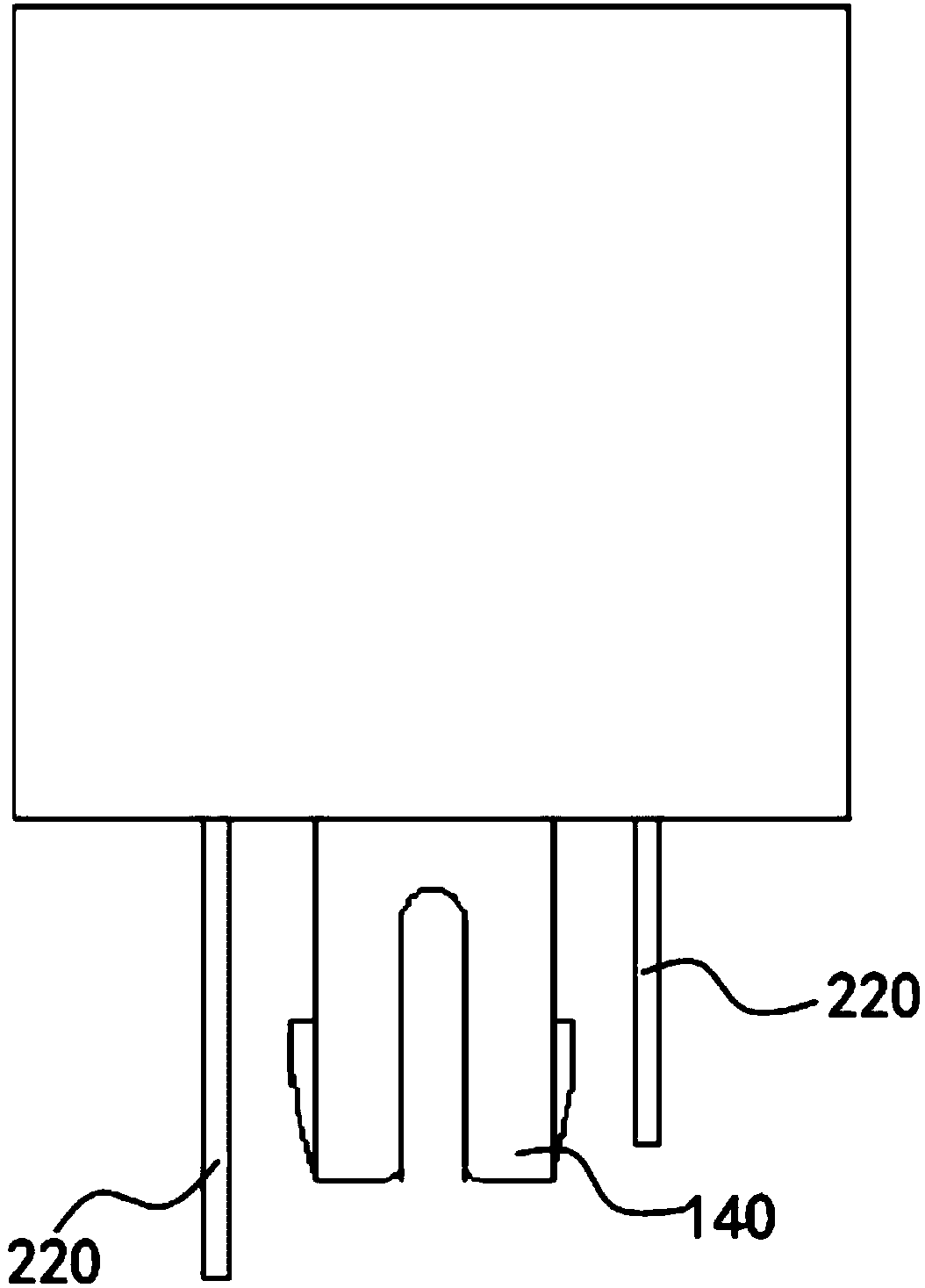
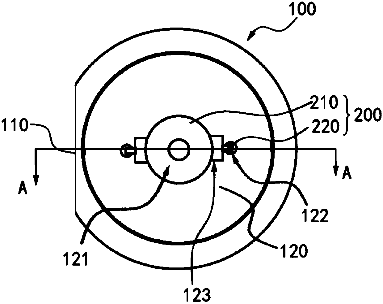
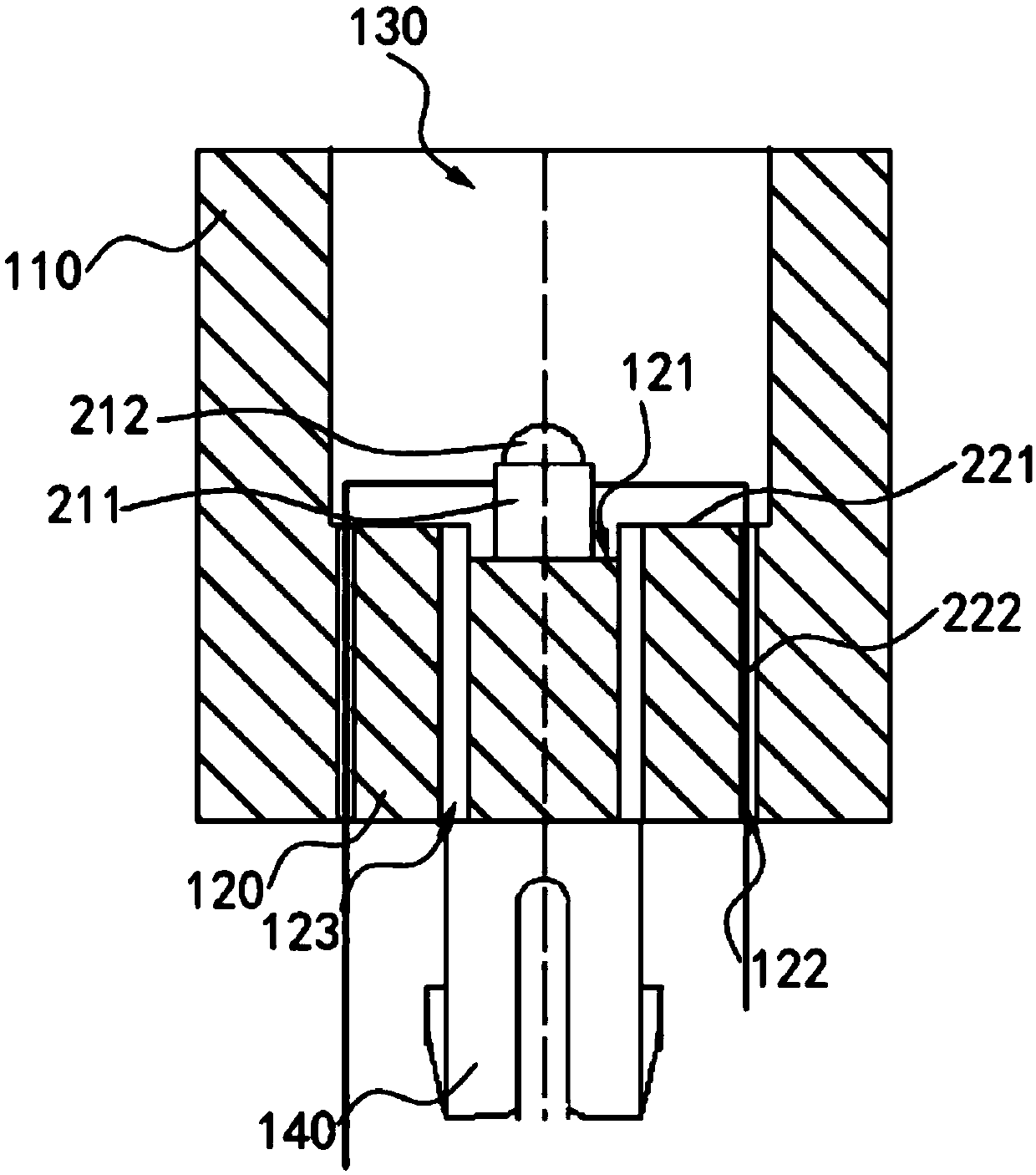
The invention provides a light-emitting device, which comprises a shell and a light-emitting member, wherein the shell is of a cylindrical structure and is provided with a cylinder body and a bottom plate, the bottom plate is fixed and sealed at the bottom cylinder opening of the cylinder body, the cylinder body and the bottom plate jointly define an inner cavity, the opening of the inner cavity is formed in the top of the cylinder body, the light-emitting member is provided with a lamp bead and two pins, the lamp bead is contained in the inner cavity, one end of each pin is connected to the lamp bead, the other end of each pin penetrates through the bottom plate and extends downwards, and the light-emitting device is configured to be connected to a circuit board through two pins. Throughthe design, according to the light-emitting device, the lamp bead is lifted by the bottom plate of the shell, and when the light-emitting device is arranged on the circuit board, the lamp bead has thehigh arrangement height relative to the circuit board compared with the existing light-emitting device, so that the novel arrangement requirement of the lamp bead in the field is met.

Description

technical field [0001] The present disclosure relates to the technical field of light emitting devices, in particular to a light emitting device. Background technique [0002] At present, the light-emitting device based on, for example, LED lamp beads as light-emitting parts, because the actual application angle of the existing LED lamp beads is relatively small, when the above-mentioned existing light-emitting devices are directly plugged into the PCB board, the setting height of the LED lamp beads is relatively low, so that It cannot meet the new requirements of the field for light-emitting devices. In addition, the above-mentioned existing light-emitting devices cannot be effectively positioned on the PCB. Contents of the invention [0003] A main purpose of the present disclosure is to overcome at least one defect of the above-mentioned prior art, and provide a light emitting device in which light emitting elements are arranged at a relatively high height. [0004] I...

Claims


Application Information

Patent Timeline
Patent Type & Authority Applications(China)
IPC IPC(8): H01L33/48H01L33/62
CPCH01L33/483H01L33/62
Inventor 季明明陈铭哲
Owner EVERLIGHT ELECTRONICS (CHINA) CO LTD
Why Eureka
Try Eureka