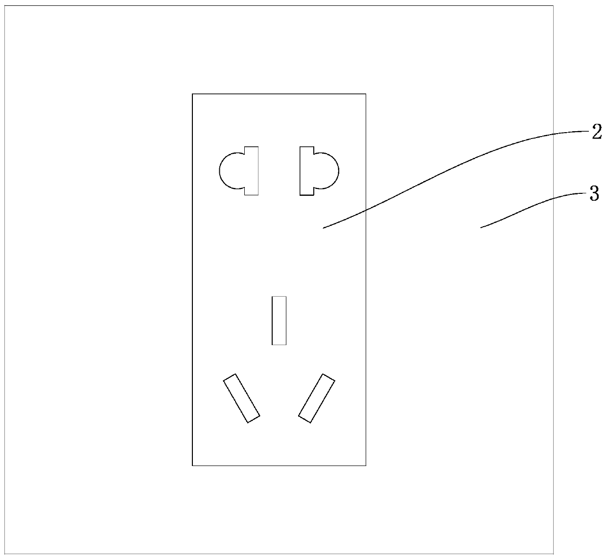
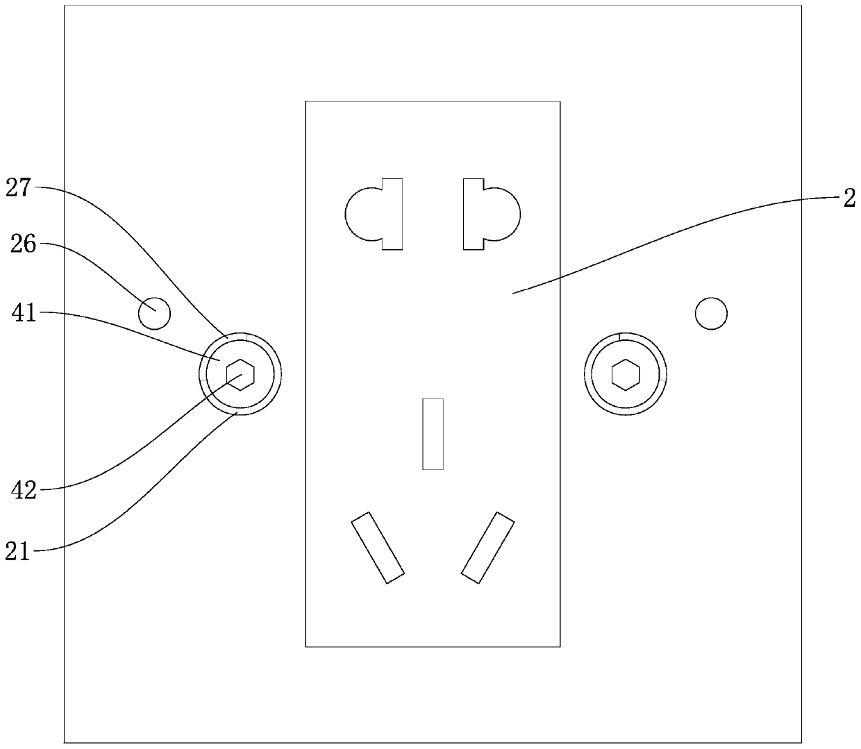
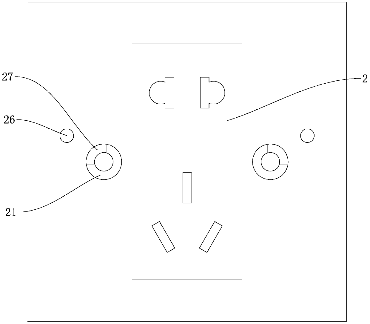
Wall socket with wiring terminals

A technology for wall sockets and terminal blocks, which is applied to parts, connections, contact parts, etc. Multiple phase wires cannot be inserted into the phase wire terminals at the same time, etc.

Active Publication Date: 2020-07-03
沈一群
View PDF4 Cites 8 Cited by
  • Summary
  • Abstract
  • Description
  • Claims
  • Application Information

AI Technical Summary

Problems solved by technology

When the current wall socket is in use, the ground wire terminal on the back of the wall socket needs to be electrically connected to the ground wire in the cassette, and the phase wire terminal on the back of the wall socket needs to be electrically connected to the phase wire in the cassette. The neutral wire terminal on the back needs to be electrically connected to the neutral wire in the cassette; however, there are often multiple ground wires, phase wires and neutral wires in the cassette, so that the ends of the multiple ground wires must be connected to the wall. The ground wire terminal on the back of the socket is electrically connected, the ends of multiple phase wires must be electrically connected to the phase wire terminal on the back of the wall socket, and the ends of multiple neutral wires must be connected to the neutral wire on the back of the wall socket Terminal electrical connection; however, due to the limited number of connections on the back of the socket panel for the ground wire terminal, phase wire terminal and neutral wire terminal, that is, it often occurs that multiple ground wires cannot be inserted into the ground wire terminal at the same time, or There will be a phenomenon that multiple phase wires cannot be inserted into the phase wire terminal at the same time, or there will be a phenomenon that multiple neutral wires cannot be inserted into the neutral wire terminal at the same time, which will cause inconvenience to the installer of the wall socket , and will affect the reliability of the connection between the wall socket and the ground, phase and neutral wires

Method used


Image

  • Wall socket with wiring terminals
  • Wall socket with wiring terminals
  • Wall socket with wiring terminals

Examples


Embodiment Construction

[0029] A number of embodiments of the present invention will be disclosed in the following figures. For the sake of clarity, many practical details will be described together in the following description. It should be understood, however, that these practical details should not be used to limit the invention. That is, in some embodiments of the invention, these practical details are not necessary. In addition, for the sake of simplifying the drawings, some well-known and commonly used structures and components will be shown in a simple schematic manner in the drawings.

[0030] In addition, in the present invention, descriptions such as "first", "second" and so on are used for description purposes only, and do not refer to the meaning of sequence or sequence, nor are they used to limit the present invention, but are only for the purpose of distinguishing the following The components or operations described by the same technical terms are merely used, but should not be underst...


PUM


Abstract

The invention discloses a wall socket with wiring terminals. The wall socket comprises a socket panel installed at the front end of a cassette. A housing is sleeved outside the front end of the socketpanel; three wiring terminal strips are embedded in the rear end of the socket panel. The three wiring terminal strips are respectively close to a ground wire wiring end of the socket panel, a phaseline wiring end of the socket panel and a zero line wiring end of the socket panel; the back part of the socket panel is provided with an embedding groove for embedding one wiring terminal strip, andthe side wall of each embedding groove is provided with a wire groove corresponding to each wiring hole in the corresponding wiring terminal strip. According to the invention, the three wiring terminal strips are embedded in the rear end of the socket panel; the three wiring terminal strips are respectively used for realizing the doubling of a plurality of ground wires, a plurality of phase wiresand a plurality of null wires, i.e., the expansion of the ground wire wiring end, the phase wire wiring end and the null wire wiring end at the back of the socket panel is realized, so that the wiringcapability of the socket panel can be improved, and convenience is brought to the installation personnel of the wall socket.

Description

technical field [0001] The invention relates to the technical field of electrical connection devices, in particular to a wall socket with connection terminals. Background technique [0002] In the building decoration process, the wall socket is an indispensable electrical connection device, which is fixed on the cassette when in use, and the cassette is pre-buried in the wall. When the current wall socket is in use, the ground wire terminal on the back of the wall socket needs to be electrically connected to the ground wire in the cassette, and the phase wire terminal on the back of the wall socket needs to be electrically connected to the phase wire in the cassette. The neutral wire terminal on the back needs to be electrically connected to the neutral wire in the cassette; however, there are often multiple ground wires, phase wires and neutral wires in the cassette, so that the ends of the multiple ground wires must be connected to the wall. The ground wire terminal on th...

Claims


Application Information

Patent Timeline
Patent Type & Authority Applications(China)
IPC IPC(8): H01R13/02H01R13/502H01R13/648H01R13/652H01R13/508H01R13/512
CPCH01R13/02H01R13/502H01R13/508H01R13/512H01R13/648H01R13/652
Inventor 沈一群
Owner 沈一群
Why Eureka
Try Eureka