Connector

A connector and external technology, applied in the direction of connection, connecting device parts, contact parts, etc., can solve the problems of poor connector tolerance, unreliable connection, etc., to improve the structure, reduce interference, and improve heat dissipation. Effect

Active Publication Date: 2020-07-03
CHINA AVIATION OPTICAL-ELECTRICAL TECH CO LTD
View PDF11 Cites 4 Cited by
  • Summary
  • Abstract
  • Description
  • Claims
  • Application Information

AI Technical Summary

Problems solved by technology

[0005] The purpose of the present invention is to provide a connector that can solve the problems of poor tolerance and unreliable connection in the prior art

Method used


Image

  • Connector
  • Connector
  • Connector

Examples


Embodiment 3

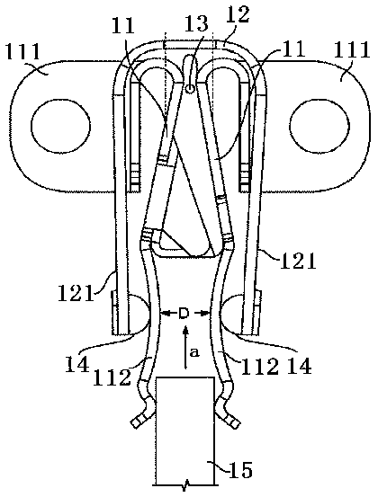
[0070] Embodiment 3 of the connector in the present invention: the difference from the above-mentioned embodiments is that in this embodiment, the force-limiting clamp is a U-shaped structure, and the bottom edge of the force-limiting clamp and the insulator face the force-limiting transmission. Between the sides of the force clamps, there is reserved space for the limit force transmission clamp to swing relative to the insulator. When the adapter insert is inserted into the socket with a certain lateral deviation, the adapter contact is applied to the two conductors. A lateral force in the sheet and pushes it to shift laterally, the limit force transmission clip can also swing by itself while transmitting the force to the other conductive sheet, and is not limited to the use of the limit force transmission clip One of the bottom edge of the insulator and the side of the insulator facing the position-limiting force-transmitting clip is provided with a convex portion, and the ot...

Embodiment 5

[0072] Embodiment 5 of the connector in the present invention: the difference from the above embodiments is that in this embodiment, the part of the conductive sheet that constitutes the insertion jaw can be a complete plate body, and the clip of the limit force transmission clip The arm directly abuts against the board surface of the board body, and is not limited to the solution of setting a comb-like structure on the conductive sheet. Or the part of the conductive sheet that constitutes the plug-in jaw is still designed as a comb-shaped structure, and the part that cooperates with the comb-shaped structure in the clamp arm of the limit force transmission clamp is no longer provided with limit ribs, but relies on the complete end surface and the comb structure. Comb structure against the top fit.

Embodiment 6

[0073] Embodiment 6 of the connector in the present invention: the difference from the above embodiments is that in this embodiment, the structure used to communicate with other contacts in the conductive sheet can be arranged at the tail end of the conductive sheet in the insertion direction , not limited to the scheme of setting the sheet-shaped outer connection section at the top position of the conductive sheet perpendicular to the insertion direction, and at this time, there is no need to make an avoidance structure for avoiding the sheet-shaped outer connection section on the housing.


PUM


Abstract

The invention relates to a connector, which can solve the problems of poor tolerance capability and unreliable connection of a connector in the prior art. The connector comprises a shell and a pair ofconducting strips. One end of each conducting strip is a fixed wiring end, the other ends of the conducting strips are oppositely arranged to form an insertion clamping opening, and an insulator is limited between the two paired conducting strips and is fixed relative to the two conducting strips in the insertion direction. The connector further comprises a limiting force transmission clamp whichis a U-shaped clamp. The conductive assembly is located in the limiting force transmission clamp, and the direction of the inserting clamping opening is consistent with the direction of an opening ofthe limiting force transmission clamp. The two clamping arms of the limiting force transmission clamp abut against the outer sides of the portions, forming the inserting clamping opening, of the twoconducting strips respectively. When the adaptive plug connector is inserted into the plug clamping opening with a certain transverse deviation, the adaptive contact piece applies a transverse actingforce to one of the two conducting strips and pushes the conducting strip to transversely shift, and the conducting strip transmits the acting force in the same direction to the other conducting stripthrough the limiting force transmission clamp, so that the other conducting strip laterally shifts towards the same side and is in contact with the adaptive plug connector.

Description

technical field [0001] The invention relates to a connector. Background technique [0002] In the prior art, the connector assembly includes a connector and an adapter connector, and the connector and the adapter connector can be inserted to transmit electric signals and optical signals. The U.S. patent document with the patent number US8388389B2 and the filing date of 2013.03.05 discloses a connector assembly. The structure of the connector assembly is as follows: figure 1 As shown, the connector assembly includes a plug-fit connector and an adapter connector. The connector mainly includes two conductive pieces 11, a spring clip 12, a fixing piece 13 and an insulating block 14. The adapter connector is provided with a clamp A bus bar that is held between two conductive sheets to achieve circuit conduction. [0003] Specifically, the two conductive sheets 11 have the same structure, and both include an ear plate 111 connected to the contact plate and a clamping portion 112...

Claims


Application Information

Patent Timeline
Patent Type & Authority Applications(China)
IPC IPC(8): H01R13/11H01R13/631H01R13/639
CPCH01R13/11H01R13/112H01R13/6315H01R13/639
Inventor 张荣团李猛薛杨扬冯冲程升升
Owner CHINA AVIATION OPTICAL-ELECTRICAL TECH CO LTD
Why Eureka
Try Eureka